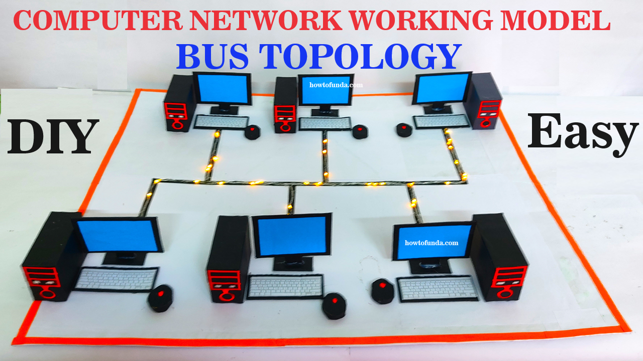
Creating a working model of a computer network using a bus topology with serial LED lights is a fantastic hands-on way to understand how devices communicate in such a network.
Here’s how you can create it:

Materials Needed:
- Cardboard
- Color paper (various colors)
- Scissors
- Glue
- Markers
- LED lights (multiple)
- Wires
- Batteries (for LED lights)
- Connectors (to connect LEDs in series)
- Desktop (2 or more)
- CPU box (represents the central bus)
- Keyboard and mouse (for each desktop)
Step by Step Video Instructions:
- Prepare the Devices:
- Cut out shapes from cardboard to represent each device. For example, rectangles for desktops, a larger rectangle for the CPU box (to represent the central bus), and smaller shapes for the keyboard and mouse.
- Use color paper to cover each cardboard shape to represent the color of each device (e.g., black for desktops, gray for the CPU box, etc.).
- Write the name of each device on its respective shape.
- Create LED Lights for Network Representation:
- Cut out small circles from cardboard and color them to represent LED lights.
- Connect the LEDs in series using wires and connectors. The LEDs should be connected one after another in a line.
- Leave enough length of wires at both ends for connecting them to the devices.
- Connect the positive (red) and negative (black) terminals of each LED with wires to the positive and negative terminals of the batteries.
- Connect the Devices in Bus Topology:
- Arrange the devices on a flat surface to represent a bus topology. The CPU box should be placed in the center, and the desktops should be connected to it in a linear manner.
- Glue the CPU box and desktops in their respective positions.
- Connect the LEDs to represent the connections between devices. For example:
- Connect an LED wire from the CPU box to the first desktop.
- Connect another LED wire from the first desktop to the second desktop, and so on.
- Use different colors for each LED wire to differentiate between connections.
- Attach Keyboard and Mouse:
- Glue the keyboard and mouse shapes next to each desktop.
- Use color paper to represent the wires connecting the keyboard and mouse to the desktop.
- Test the Model:
- Ensure all LEDs are connected properly and are lighting up.
- Move the devices closer or farther apart to simulate the network’s behavior.
- Test the connections by pretending to send data between devices.
- Display and Explanation:
- Display the model in the classroom or at home.
- Provide an explanation of how the bus topology works, with the CPU box acting as a central bus and each desktop connected to it in a linear manner.
- Explain how data travels along the bus and how each device can communicate with the others.
This model not only helps in understanding bus topology but also makes learning about computer networks interactive and enjoyable!