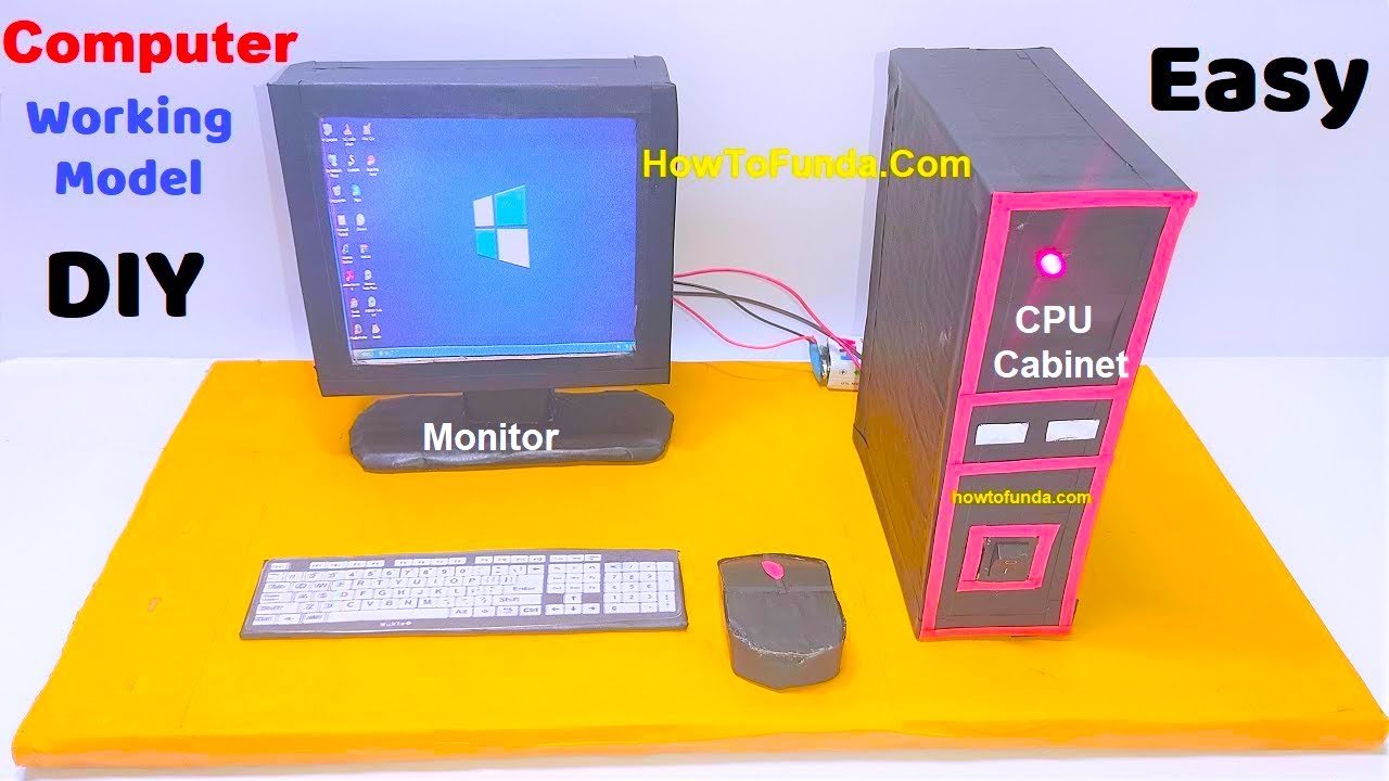
In this project, we’ll create a basic computer working model that includes a glowing monitor and CPU.

This is a simplified representation, but it provides a visual demonstration of how a computer’s components work together. Here are the steps:
Materials Needed:
- Cardboard sheets (for the base and components)
- Colored paper or construction paper
- Scissors
- Glue or adhesive tape
- Markers or pens
- LED lights (with resistors)
- 9V battery
- Battery clip with connector
- Copper wires
Building the Computer Working Model:
1. Creating the Base:
Step 1: Cut out a rectangular piece of cardboard to serve as the base of your computer model. This will provide stability for your components.
2. Designing the Monitor:
Step 2: Cut out a rectangular piece of cardboard to represent the monitor. This will be the screen.
Step 3: Attach a piece of colored paper to the front of the monitor to serve as the display. You can draw a desktop or any image you like on it.
Step 4: Cut out a smaller piece of colored paper in the shape of a power button and attach it to the monitor.
Step 5: Create small rectangular LED holders from cardboard. Attach these holders behind the monitor where you want the monitor’s power indicator to be.
Step 6: Attach LED lights (with resistors) to the holders. Connect the positive (longer) leg of the LED to the positive terminal of the battery clip and the negative (shorter) leg to the negative terminal using copper wires.
3. Building the CPU:
Step 7: Cut out a rectangular piece of cardboard to represent the CPU unit.
Step 8: Use colored paper to add details to the CPU, such as buttons, vents, and ports.
Step 9: Create a small rectangular LED holder from cardboard and attach it to the CPU unit where you want the CPU’s power indicator to be.
Step 10: Attach an LED light (with a resistor) to the holder. Connect the positive (longer) leg of the LED to the positive terminal of the battery clip and the negative (shorter) leg to the negative terminal using copper wires.
4. Connecting the Components:
Step 11: Position the monitor and CPU unit on the base, securing them with glue or adhesive tape.
5. Adding Power Supply:
Step 12: Attach the 9V battery to the base using adhesive tape.
Step 13: Connect the battery clip to the battery. Make sure the positive and negative terminals are correctly aligned.
6. Powering the LEDs:
Step 14: Connect the LED wires from both the monitor and CPU to the battery clip. Ensure the positive and negative connections are accurate.
7. Testing:
Step 15: Turn on the battery and observe as the LEDs in the monitor and CPU light up, simulating a powered computer.
Your simple computer working model is now complete!
This basic representation provides a visual demonstration of a computer’s key components, with glowing LEDs to simulate power indicators.
It’s a creative way to illustrate the basic concept of how a computer functions.