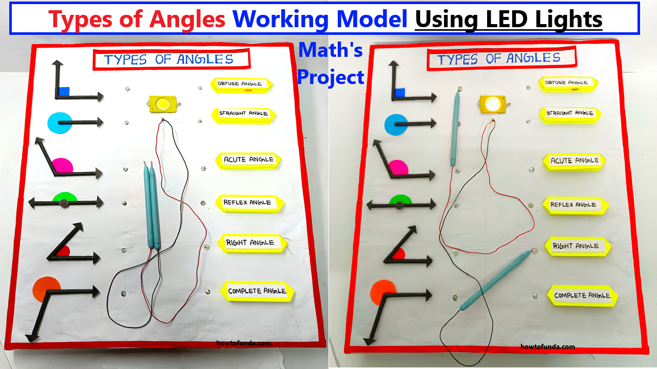
Concept:
This working model demonstrates different types of angles (acute, obtuse, right, straight, etc.) and their properties. Using LED lights, a 9V battery, a buzzer, and conductive materials like nails or wires, the project enables students to match the name of an angle type with its visual representation or degree measure.

Materials Required:
LED lights (different colors for each angle type)
- 9V battery and battery clip
- Buzzer
- Nails or conductive pins
- Wires (for connections)
- Cardboard or wooden board (as the base)
- Printed or drawn angle diagrams (acute, obtuse, right, etc.)
- Labels for angle types (e.g., “Acute Angle,” “Obtuse Angle”)
- Copper tape or insulated wires for circuits
- Resistors (to protect LEDs)
Steps to Build:
- Prepare the Board:
- Divide the board into two sections:
- Ride Side: Labels for types of angles (e.g., “Acute Angle”).
- Left Side: Drawings or visual representations of angles, each with a specific degree measurement.
- Divide the board into two sections:
- Install Nails or Pins:
- Place nails or conductive pins below each label and angle representation.
- Connect the correct pairs of nails (left side to right side) using hidden wires under the board.
- Set up the Circuit:
- Use wires to connect nails for each pair (label and angle) in a circuit containing:
- An LED and a buzzer.
- A resistor to limit current for the LED.
- Connect the circuits to a 9V battery. Use diodes or unique paths to ensure only correct matches complete a circuit.
- Use wires to connect nails for each pair (label and angle) in a circuit containing:
- Matching Mechanism:
- Each pair of nails corresponds to a specific type of angle.
- When the correct connection is made (e.g., using a wire or clip), the circuit closes, and:
- The LED lights up, showing a correct match.
- The buzzer sounds, providing auditory feedback.
- Test the Model:
- Verify that the LED and buzzer activate only for correct matches.
- Ensure incorrect connections do not complete any circuit.
Usage:
Objective: Match the name of the angle type (e.g., “Right Angle”) with its correct visual representation (e.g., 90° angle diagram).
- Process: Connect a wire or clip from a label on the left to an angle diagram on the right.
- Feedback:
- Correct match: LED lights up and buzzer sounds.
- Incorrect match: No response.

