
An Algebraic Expressions Working Model is an interactive educational tool designed to help students understand and match algebraic expressions effectively. This model uses LED lights, a 9V battery, a buzzer, and conductive materials like nails or wires to create a “match board” concept. The left side of the board displays a series of algebraic expressions (e.g., (a + b)2 , while the right side displays equivalent or related expressions (e.g., a2 + 2ab + b2).
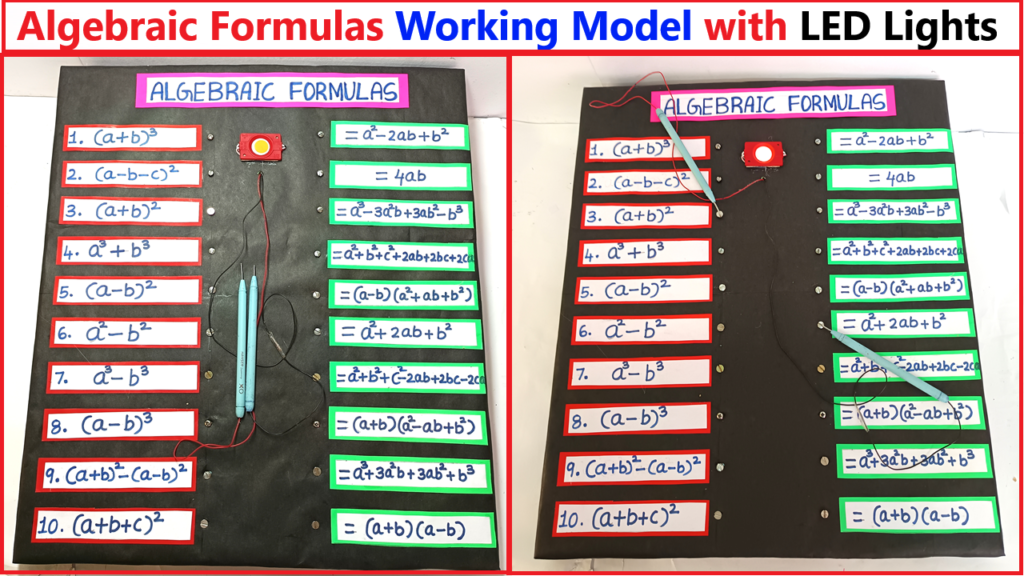
When a correct match is made between the left and right expressions by connecting wires or clips to the appropriate points, an LED lights up and a buzzer sounds, providing immediate feedback. The circuit is designed so only correct matches complete the electrical connection, making the learning process engaging and hands-on.
This project combines basic electronics and mathematics to enhance conceptual understanding through experimentation and interactive learning. It’s ideal for science fairs, exhibitions, or classroom activities.
To create your algebraic expressions working model:
Materials Required:
- LED lights (multiple colors for differentiation)
- 9V battery and a battery clip
- Buzzer
- Nails or conductive pins (to act as connectors)
- Wires (to connect components)
- Cardboard or wooden board (as the base)
- Algebraic expressions printed or written on paper
- Copper tape or conductive wire for creating circuits
- Resistors (to prevent LEDs from burning out)
- Switches (optional, for resetting connections)
Steps to Build Algebraic expressions working model:
- Prepare the Match Board:
- Divide the board into two sections: the left side for algebraic expressions and the right side for their matches.
- Write or attach printed expressions on both sides, ensuring the correct pairs are pre-determined.
- Set up Nails/Connectors:
- Insert nails or conductive pins below each expression on both sides.
- Ensure nails on one side (left) are connected to nails on the corresponding side (right) through a hidden circuit.
- Create the Electrical Circuit:
- Connect each pair of nails (one on the left and its corresponding match on the right) using wires.
- For each circuit, include an LED and a buzzer.
- Connect all circuits to the 9V battery. Use resistors in series with LEDs to control current flow.
- Ensure Match Concept:
- Only the correct pair of nails should complete a circuit. To do this, use diodes to create unique paths for each pair.
- Add Feedback Mechanism:
- When a match is made (e.g., by connecting wires or inserting a conductive clip between nails), the circuit closes.
- The LED lights up and the buzzer sounds, indicating a correct match.
- Test the Model:
- Ensure that incorrect matches do not complete any circuit.
- Adjust connections or add additional resistors if needed.
Usage:
- The student touches a wire or clip to a nail on the left (expression side) and then to a nail on the right (matching side).
- If the match is correct, the LED and buzzer activate.
- If the match is incorrect, no feedback is provided.