
A parallel circuit is a basic electrical circuit configuration where the components are connected in multiple paths, allowing current to flow through each component independently.
In a parallel circuit, the voltage across all components is the same, and the total current entering the circuit is divided among the components. Here’s a more detailed working model with explanation of how a parallel circuit works:
Creating a working model of an electric circuit with multiple LED lights in parallel is a great way to understand the principles of parallel circuits.
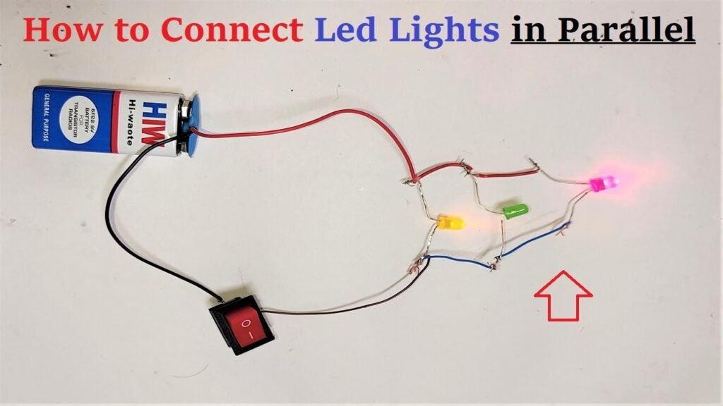
Here’s a step-by-step guide on how to set up the circuit using 3 LED lights, a 9V battery, a switch, and wires:
Materials You’ll Need:
- 3 LED lights (different colors if possible)
- 9V battery
- Toggle switch
- Connecting wires with alligator clips or jumper wires
- Breadboard (optional, for easier connections)
Steps to Build the Circuit:
- Prepare the Components:
- Identify the positive (+) and negative (-) leads of the LED lights. The longer lead is typically the positive one.
- Connect the alligator clips or jumper wires to the battery, switch, and LED lights.
- Place the LED Lights:
- Arrange the LED lights side by side on a surface or on a breadboard. Ensure that their positive leads are on one side and their negative leads on the other.
- Connect the Positive Side:
- Connect the positive lead of the battery to one side of the toggle switch using a wire or alligator clip.
- Connect the other side of the toggle switch to the positive leads of all three LED lights using separate wires.
- Connect the Negative Side:
- Connect the negative lead of the battery directly to the negative leads of all three LED lights using separate wires.
- Toggle Switch Connection:
- Connect the remaining terminal of the toggle switch to the negative lead of the battery using a wire.
- Complete the Circuit:
- Ensure that all components are securely connected, and there are no loose connections or exposed wires.
- Test the Circuit:
- Turn on the toggle switch to complete the circuit.
- All three LED lights should light up in parallel, meaning that each LED gets the full voltage of the battery.
- Observe the Results:
- Observe that all three LED lights are equally bright, indicating that they receive the same voltage in a parallel circuit.
By setting up this parallel circuit with multiple LED lights, you’ll be able to see how parallel connections ensure that each component receives the same voltage and operates independently of the others. This model can help you understand the basics of parallel circuits and how devices in such circuits share the voltage equally.
questions asked in science exhibition on parallels circuit with answers
Question 1: What is a parallel circuit?
Answer: A parallel circuit is an electrical circuit configuration where components are connected in multiple paths, allowing current to flow through each component independently. The voltage across components is the same, and the total current is divided among them.
Question 2: How does the current flow in a parallel circuit?
Answer: In a parallel circuit, each component has its own independent path for current flow directly from the power source. The current through each component is determined by its resistance.
Question 3: What is the advantage of a parallel circuit compared to a series circuit?
Answer: In a parallel circuit, if one component fails or is disconnected, the others continue to operate unaffected. This is a significant advantage over series circuits, where the failure of one component can disrupt the entire circuit.
Question 4: How is the voltage distributed in a parallel circuit?
Answer: The voltage across all components in a parallel circuit is the same. This means that the potential difference between the positive and negative terminals of the power source remains constant for all components.
Question 5: What happens to the total resistance when more resistors are added to a parallel circuit?
Answer: In a parallel circuit, adding more resistors decreases the total resistance. This is because the reciprocal of the total resistance is the sum of the reciprocals of the individual resistances.
Question 6: Can you explain how Ohm’s Law applies to a parallel circuit?
Answer: In a parallel circuit, Ohm’s Law applies to each component individually. The current through a resistor is inversely proportional to its resistance. Components with lower resistance will allow more current to flow.
Question 7: How do the brightness and resistance of bulbs in a parallel circuit relate?
Answer: In a parallel circuit with bulbs (incandescent lamps), the brightness of each bulb is not affected by the others. Lower resistance bulbs will draw more current and be brighter.
Question 8: What are some practical applications of parallel circuits?
Answer: Parallel circuits are used in applications where components need to operate independently and where a consistent voltage across components is required. Examples include household electrical wiring, appliances, and electronic devices.
Question 9: How does adding more components affect the total current in a parallel circuit?
Answer: Adding more components to a parallel circuit increases the total current entering the circuit. This is because each component provides an additional pathway for current flow.
Question 10: How is the total current in a parallel circuit divided among the components?
Answer: The total current entering a parallel circuit is divided among the components based on their individual resistances. Components with lower resistance draw more current.