A series circuit is a basic electrical circuit configuration where the components are connected end-to-end in a single path, forming a loop for the current to flow. In a series circuit, the same current flows through all components, and the total voltage across the circuit is divided among the components.
Here’s a more detailed explanation of how a series circuit works:
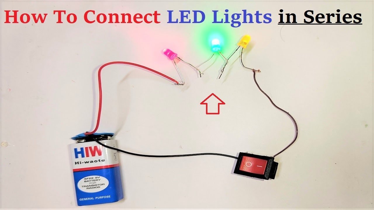
Creating a working model of an electric circuit with multiple LED lights in series is a great way to understand the principles of series circuits.

Here’s a step-by-step guide on how to set up the circuit using 3 LED lights, a 9V battery, a switch, and wires:
Materials You’ll Need:
- 3 LED lights (different colors if possible)
- 9V battery
- Toggle switch
- Connecting wires with alligator clips or jumper wires
- Breadboard (optional, for easier connections)
Steps to Build the Series Circuit Working Model :
- Prepare the Components:
- Identify the positive (+) and negative (-) leads of the LED lights. The longer lead is typically the positive one.
- Connect the alligator clips or jumper wires to the battery, switch, and LED lights.
- Place the LED Lights:
- Arrange the LED lights in a row on a surface or on a breadboard. Connect their positive leads to their negative leads in a series.
- Connect the Positive Side:
- Connect the positive lead of the battery to one side of the toggle switch using a wire or alligator clip.
- Connect the other side of the toggle switch to the positive lead of the first LED light.
- LED Series Connection:
- Connect the negative lead of the first LED light to the positive lead of the second LED light.
- Connect the negative lead of the second LED light to the positive lead of the third LED light.
- Connect the Negative Side:
- Connect the negative lead of the third LED light to the negative lead of the battery using a wire.
- Toggle Switch Connection:
- Connect the remaining terminal of the toggle switch to the negative lead of the battery using a wire.
- Complete the Circuit:
- Ensure that all components are securely connected, and there are no loose connections or exposed wires.
- Test the Circuit:
- Turn on the toggle switch to complete the circuit.
- All three LED lights should light up in series, one after the other.
- Observe the Results:
- Observe that the brightness of the LED lights may vary. The LED at the beginning of the series may be brighter than the one at the end due to voltage drop.
By setting up this series circuit with multiple LED lights, you’ll be able to see how series connections result in a single path for current flow, causing the LED lights to illuminate sequentially. This model can help you understand the basics of series circuits and how the voltage is divided among components in such circuits.
questions asked in science exhibition on series circuit with answers
Question 1: What is a series circuit?
Answer: A series circuit is an electrical circuit configuration where components are connected end-to-end in a single path, forming a loop for the current to flow. In a series circuit, the same current flows through all components.
Question 2: How does the current flow in a series circuit?
Answer: In a series circuit, the current flows through each component in succession, from the positive terminal of the power source to the negative terminal. There is only one path for the current to follow.
Question 3: What happens to the current if one component in a series circuit fails?
Answer: If one component in a series circuit fails or is disconnected, the entire circuit becomes open, and the current cannot flow. This is because there is only one path for the current to follow.
Question 4: How is the voltage distributed in a series circuit?
Answer: The total voltage provided by the power source is shared among the components in a series circuit. Each component experiences a voltage drop proportional to its resistance, and the sum of the voltage drops equals the total voltage.
Question 5: How do the brightness and resistance of bulbs in a series circuit relate?
Answer: In a series circuit with bulbs (incandescent lamps), the brightness of the bulbs is affected by the total current passing through them. Higher resistance bulbs will be dimmer, while lower resistance bulbs will be brighter.
Question 6: Can you explain how Ohm’s Law applies to a series circuit?
Answer: Ohm’s Law (V = IR) applies to each component in a series circuit. The voltage drop across a resistor is directly proportional to its resistance. This means that higher resistance components will have larger voltage drops.
Question 7: How does the total resistance in a series circuit change when more resistors are added?
Answer: The total resistance in a series circuit increases when more resistors are added. This is because the resistances add up, leading to a higher overall resistance in the circuit.
Question 8: What are some practical applications of series circuits?
Answer: Series circuits are used in applications where components need to share the same current, such as in decorative lighting, holiday lights, and some types of electronic devices.
Question 9: What are the advantages and disadvantages of series circuits?
Answer: Advantages include a simple construction and equal current through components. Disadvantages include the failure of one component affecting the entire circuit and reduced brightness with more components.
Question 10: How does a series circuit differ from a parallel circuit?
Answer: In a series circuit, components are connected end-to-end, and the same current flows through all components. In a parallel circuit, components are connected in separate paths, and the voltage across all components is the same while the current varies.