
1. Introduction
Good morning, respected judges, teachers, and my dear friends.
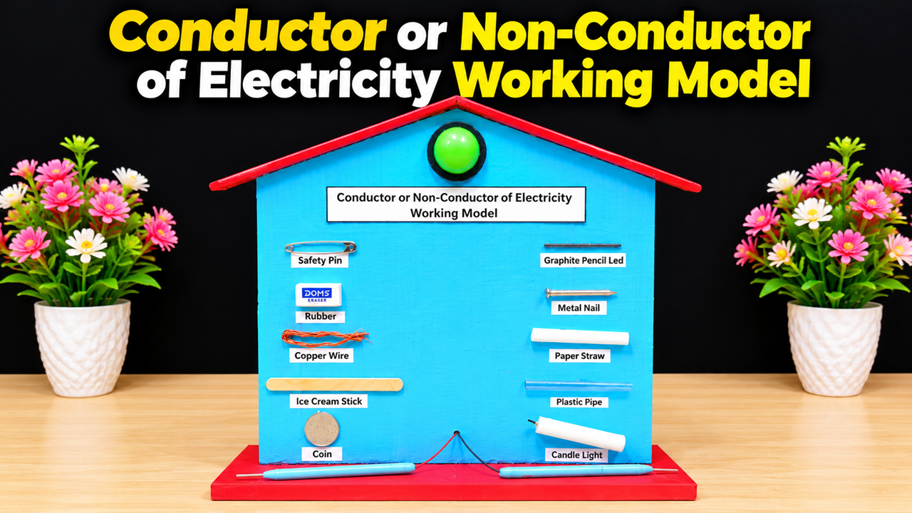
Today, I am going to present my science project, “Conductor or Non-Conductor of Electricity Working Model.”
Electricity plays an important role in our daily lives. We use it to operate lights, fans, computers, mobile phones, and many other devices. However, all materials do not allow electric current to pass through them in the same way.
Some materials allow electricity to flow easily. These are called electrical conductors. Other materials resist the flow of electric current and are commonly called insulators or non-conductors.
My working model demonstrates how different everyday materials can be tested to identify whether they conduct electricity.
2. Aim of the Project
The main objectives of this project are:
- To understand the difference between conductors and insulators.
- To test common materials using a simple electric circuit.
- To learn how electrical conductivity affects the flow of current.
- To understand the importance of electrical safety.
- To demonstrate a simple physics experiment using everyday materials.
3. Materials Required
The following materials are required to prepare this model:
- Thick cardboard sheets for the base and upright panel.
- Blue and red chart paper or coloured foam sheets.
- A low-voltage battery, such as a 3V battery pack.
- A small low-voltage LED or indicator lamp.
- A suitable current-limiting resistor for the LED.
- Connecting wires with insulated ends.
- Two test probes or crocodile clips.
- A switch, if required.
- Small samples of copper wire, a metal nail, a coin, a safety pin, a graphite pencil lead, a rubber eraser, an ice-cream stick, a paper straw, a plastic pipe, and a candle.
- Glue, scissors, ruler, markers, and labels.
The model should use a low-voltage battery circuit only. Never connect the experiment to household electricity.
4. Making Process
Step 1: Prepare the base
Take a thick cardboard sheet and cut it into a rectangular base. Cover it with red chart paper or foam sheet. Make sure the base is strong enough to support the upright panel and test samples.
Step 2: Construct the main panel
Cut a large rectangular piece of cardboard and cover it with blue chart paper. Fix it vertically to the base using glue and additional cardboard supports. Add a title at the top: “Conductor or Non-Conductor of Electricity.”
Step 3: Arrange the material samples
Divide the panel into two columns. Place labels and samples in suitable positions.
The first column can contain copper wire, a metal nail, a coin, a safety pin, a graphite pencil lead, and an ice-cream stick.
The second column can contain a rubber eraser, a paper straw, a plastic pipe, and a candle.
Attach each sample securely while leaving the appropriate test area accessible.
Step 4: Prepare the testing circuit
Connect the battery, current-limiting resistor, LED, and test probes in series. Leave a small gap between the two probes. This gap is where each material will be tested.
The circuit should be designed so that current can flow only when a suitable conducting sample completes the connection between the probes.
Step 5: Install the indicator
Mount the LED in a visible position on the panel. When a conducting sample bridges the two probes, the circuit should be completed and the LED should light up.
If the LED does not light, first check the battery, LED polarity, wire connections, and contact between the probes and the sample.
Step 6: Label and decorate the model
Add clear labels to all the samples. You can also add a small explanation board showing “LED ON = Conducting Path” and “LED OFF = No Detectable Current.”
Finally, check all connections and make sure no exposed wire ends can accidentally touch one another.
5. Working Principle
The working principle of this model is based on electrical conductivity and the completion of an electric circuit.
An electric circuit needs a complete conducting path for current to flow. When a material is placed between the two test probes, it may complete the circuit.
If the material conducts enough current, the LED lights up. This indicates that the material allows electric current to pass through the test circuit.
If the LED remains off, the material may be an insulator, or it may not conduct enough current to make the LED glow. Poor contact, a weak battery, or an incorrectly connected LED can also affect the result.
Therefore, the circuit and connections should be checked before drawing a conclusion about a material.
6. Testing Different Materials
During the demonstration, I will test the materials one by one.
- Copper wire: Copper is a good electrical conductor and should allow current to flow.
- Metal nail: A typical metal nail conducts electricity.
- Coin: Most common metal coins conduct electricity, depending on their composition.
- Safety pin: A metal safety pin generally conducts electricity.
- Graphite pencil lead: Graphite conducts electricity, although its resistance is higher than that of copper.
- Rubber eraser: Rubber is generally an electrical insulator.
- Plastic pipe: Most common plastics are electrical insulators.
- Paper straw: Dry paper generally has high electrical resistance.
- Ice-cream stick: Dry wood generally conducts poorly and behaves as an insulator in this simple test.
- Candle: Candle wax is an electrical insulator.
The results can vary with the material’s composition, moisture, surface coating, and contact quality. This experiment provides a basic demonstration rather than a precise measurement of conductivity.
7. Demonstration at the Exhibition
First, I will show the complete circuit and explain the role of the battery, LED, wires, and test probes.
Next, I will place a copper wire between the probes. The LED should glow, showing that copper conducts electricity.
Then, I will test a metal nail, a coin, and a safety pin. These samples should also allow current to flow.
Finally, I will test a rubber eraser, plastic pipe, and dry paper straw. The LED should remain off because these materials generally do not conduct enough current in this setup.
I will record the results in two groups: conductors and insulators. This will help everyone compare the properties of different materials.
8. Applications and Electrical Safety
Conductors such as copper are commonly used inside electrical wires because they carry current efficiently. Insulating materials such as rubber and plastic are used around wires and cables to reduce the risk of electric shock.
This project helps students understand why electrical wires contain both conducting and insulating materials.
For safety, the experiment must use only a low-voltage battery. Never test wet materials, unknown chemicals, or household electrical outlets. Do not touch bare electrical connections while the circuit is powered.
9. Conclusion
To conclude, my Conductor or Non-Conductor of Electricity Working Model demonstrates that different materials have different electrical properties. Metals generally conduct electricity well, while materials such as rubber, plastic, and dry candle wax usually act as insulators.
Through this project, I learned about electric circuits, electrical conductivity, testing methods, and the importance of electrical safety.
My message is: “Understand Electricity, Choose the Right Materials, and Always Follow Electrical Safety Rules.”
Thank you, everyone!
Learn, Create, and Innovate!