
#computerproject #inputdevices #outputdevices #projectmodel #diy #howtofunda
Introduction:
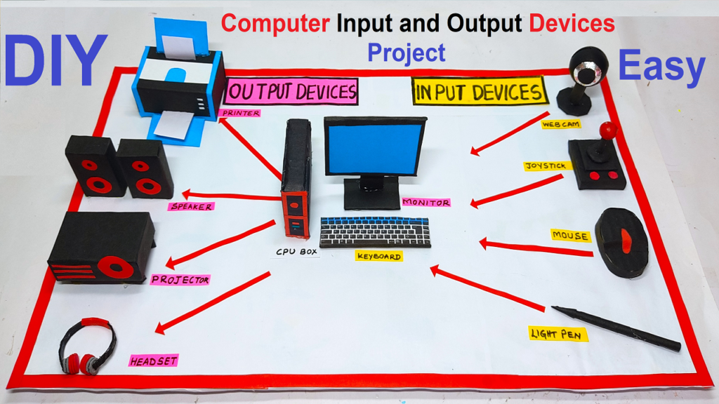
In this project, we will create a detailed model of a computer setup, complete with various input and output devices. Using basic materials like cardboard and colored paper, we’ll construct a tangible representation of a functional computer system.
This hands-on project not only reinforces understanding but also provides a visual aid to demonstrate the interactions between different devices.
Let’s dive into the step-by-step process of building this comprehensive computer model!
Materials Needed:
- Cardboard sheets
- Colored paper or construction paper
- Scissors
- Glue or adhesive tape
- Markers or pens
- Ruler
- Pencil
- Craft knife (optional, for precise cutting)
Building the Computer Model:
1. Creating the CPU (Central Processing Unit):
Step 1: CPU Structure
- Draw and cut out a rectangular piece of cardboard to represent the CPU. This will be the central processing unit of the computer.
Step 2: Adding Details
- Use colored paper to add details to the CPU, such as vents, ports, and buttons. This adds a realistic touch to the model.
2. Designing the Monitor:
Step 3: Monitor Frame
- Cut out a large rectangular piece of cardboard to form the frame of the monitor. This will be the screen where output is displayed.
Step 4: Display Screen
- Cut a piece of colored paper to fit within the frame, representing the monitor screen. Glue or tape it securely in place.
Step 5: Monitor Stand
- Create a small rectangular base for the monitor stand and attach it to the bottom of the frame. This will support the monitor.
Building the Output Devices Model:
1. Speakers:
Step 1: Creating the Main Frame
- Draw and cut out two rectangular pieces of cardboard to form the main bodies of the speakers. These will serve as the enclosures.
Step 2: Adding Speaker Grilles
- Cut out circular pieces of colored paper and attach them to the front of each speaker to represent the speaker grilles.
Step 3: Detailing and Controls
- Use markers to add details such as volume knobs, power buttons, and connectivity ports.
2. Printer:
Step 4: Printer Body
- Design and cut out a rectangular piece of cardboard to form the body of the printer. This will be the main structure.
Step 5: Paper Tray and Output Tray
- Attach smaller rectangular pieces at the top and bottom to depict the paper tray and output tray respectively.
Step 6: Printing Panel and Buttons
- Add buttons and a control panel using colored paper to represent the interface of the printer.
3. Projector:
Step 7: Projector Body
- Create a box-like structure using cardboard to serve as the body of the projector. This will be the main housing.
Step 8: Lens and Connectivity Ports
- Cut out a circular piece of colored paper to represent the lens. Add small rectangular pieces to depict connectivity ports.
Step 9: Controls and Ventilation
- Attach buttons and vents using colored paper to simulate the control panel and cooling system of the projector.
4. Headset:
Step 10: Headset Band
- Cut out a strip of cardboard to form the band of the headset. This will be the part that goes over the user’s head.
Step 11: Ear Cups and Microphone
- Create two cup-like shapes for the ears and a smaller cylindrical shape for the microphone. Attach them to the band.
Step 12: Detailing and Adjustments
- Use colored paper to add cushioning on the ear cups. Add controls and adjustments like volume buttons or sliders.
Building the Input Devices Model:
1. Webcam:
Step 1: Webcam Frame
- Draw and cut out a rectangular piece of cardboard to form the frame of the webcam. This will represent the outer structure of the device.
Step 2: Lens and Sensors
- Cut out a smaller rectangle within the frame to simulate the lens. Attach a small piece of colored paper to depict the webcam’s lens and sensors.
2. Joystick:
Step 3: Joystick Base
- Design and cut out a circular or oval-shaped cardboard piece to serve as the base of the joystick. This will be the foundation for the control stick.
Step 4: Control Stick
- Create a smaller, elongated piece of cardboard and attach it vertically to the center of the base. This represents the control stick of the joystick.
Step 5: Buttons
- Attach small, colored paper circles around the control stick to symbolize the buttons of the joystick.
3. Light Pen:
Step 6: Light Pen Body
- Cut out a thin, elongated piece of cardboard to represent the body of the light pen. This will be the part held by the user.
Step 7: Light Sensor
- Attach a small, circular piece of colored paper at the tip of the light pen to depict the light sensor.
4. Mouse:
Step 8: Mouse Body
- Design and cut out a slightly curved, oval-shaped cardboard piece to mimic the body of a mouse. This will represent the main structure.
Step 9: Buttons and Scroll Wheel
- Attach small, colored paper circles to indicate the primary and secondary buttons. Add a thin strip of colored paper for the scroll wheel.
5. Keyboard:
Step 10: Keyboard Structure
- Draw and cut out a rectangular piece of cardboard, representing the main body of the keyboard. Add an additional strip at the bottom for support.
Step 11: Keys
- Create individual rectangular keys from colored paper and attach them in rows on the keyboard structure. Label each key with letters, numbers, or symbols.
5. Connecting the Devices:
Step 10: Cables and Ports
- Use colored paper strips to represent cables and connectors. Attach them realistically from the CPU to the monitor, keyboard, mouse, speakers, and microphone.
6. Creating a Desk and Chair:
Step 11: Desk
- Cut out a large rectangular piece of cardboard to form the desk. Attach smaller rectangles to the sides as legs.
Step 12: Chair
- Design a chair shape on cardboard and cut it out. Add backrest and seat details using colored paper. Place it in front of the desk.
7. Fine Details and Customization:
Step 13: Buttons, Labels, and Screens
- Use markers to add buttons, labels, and screens on the CPU, monitor, keyboard, and mouse to simulate a realistic appearance.