
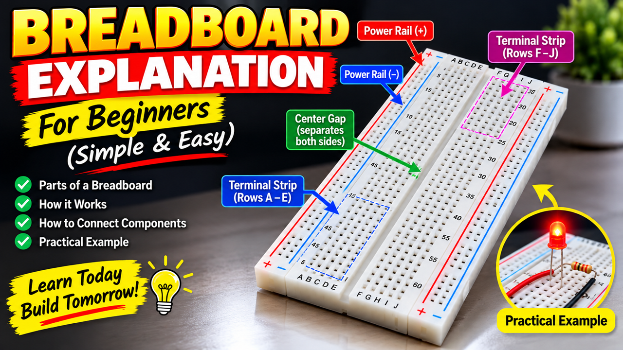
A breadboard is one of the most useful tools for learning electronics and building simple circuits. It allows us to connect electronic components such as LEDs, resistors, sensors, switches, buzzers, and jumper wires without soldering. Because components can be inserted and removed easily, a breadboard is especially useful for students, beginners, and science-project models.
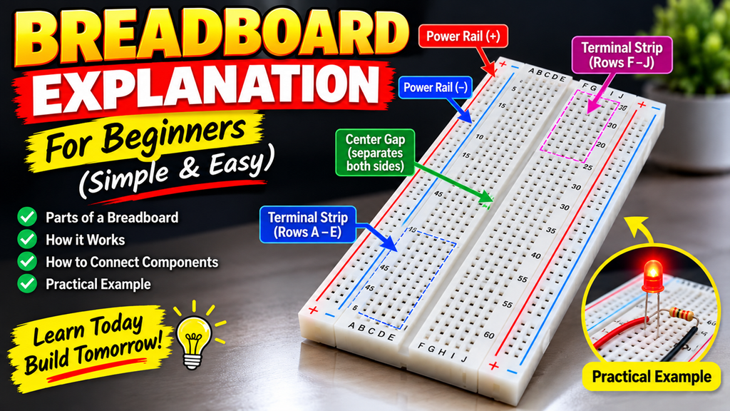
A typical breadboard has three important sections: power rails, terminal strips, and the center gap. Understanding these three parts makes it much easier to build electronic circuits.
1. Power Rails
The long lines running along the sides of the breadboard are called power rails. They are normally marked with a red (+) line and a blue or black (–) line.
The red rail is generally used for positive voltage, such as 5V from an Arduino. The blue or black rail is normally used for GND (ground).
For example, when building an Arduino project, we can connect the Arduino’s 5V pin to the positive power rail and the Arduino’s GND pin to the negative power rail. Components connected to these rails can then receive power conveniently.
It is important to remember that some breadboards have power rails that are split in the middle. In such cases, the two sections may not be electrically connected unless we connect them using a jumper wire.
2. Terminal Strips
The main area of the breadboard is called the terminal strip. It contains many small holes arranged in rows and columns.
On one side of the center gap, holes in the same group of five are electrically connected internally. The same principle applies to the five holes on the other side. This allows several component leads or jumper wires to be connected together without physically joining them with wires.
For example, if one end of a resistor is inserted into a particular row, another jumper wire placed in the same connected group can electrically connect to that resistor.
However, the five holes on one side of the breadboard are not connected to the five holes on the opposite side. The center gap separates the two sides.
3. Center Gap
The long gap running through the middle of the breadboard is called the center gap. It separates the left and right terminal strips.
The center gap is particularly useful when using integrated circuits (ICs). An IC can be placed across the gap so that its pins on opposite sides do not accidentally become connected.
Practical Example
A simple LED circuit is a good way for beginners to understand a breadboard. An LED can be connected in series with a resistor to a power supply. The resistor limits the current flowing through the LED and helps prevent damage.
For an Arduino project, the same breadboard can be used to connect sensors, LEDs, buzzers, and other components. Jumper wires can carry signals between the Arduino and the components while the power rails distribute 5V and GND.
Important Tips
Always check the breadboard connections before switching on your circuit. Make sure positive and ground are not accidentally shorted. Use the correct resistor value for LEDs and check the polarity of components such as LEDs and capacitors.
The biggest advantage of a breadboard is its simplicity and flexibility. You can experiment, make changes, troubleshoot problems, and reuse the same components without soldering.
For beginners, learning how the power rails, terminal strips, and center gap work is an important first step toward building Arduino projects and electronic circuits. Once these basic connections are understood, creating practical projects becomes much easier.