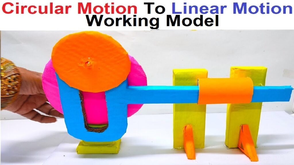
Introduction to Converting Circular Motion to Linear Motion:
Converting circular motion to linear motion is a fascinating engineering concept used in various machines and mechanisms.
This process involves transforming the rotational movement of a circular object into a straight-line motion.
Let’s explore the basics of how this conversion works:
Understanding Circular and Linear Motion:
- Circular Motion:
- Circular motion involves an object moving in a circular path around a fixed point, like a spinning wheel or the rotation of a gear.
- Linear Motion:
- Linear motion is the straightforward movement of an object in a straight line, like pushing a cart or sliding a drawer.
Conversion Mechanisms:
- Crank and Slider Mechanism:
- One common method for converting circular motion to linear motion is the crank and slider mechanism. It consists of a rotating crank (circular motion) connected to a slider (linear motion) that moves back and forth.
- Cam and Follower System:
- In a cam and follower system, a rotating cam imparts motion to a follower, resulting in linear movement. The shape of the cam determines the pattern of linear motion.
- Rack and Pinion System:
- A rack and pinion system involves a rotating gear (pinion) engaging with a flat bar with teeth (rack). As the pinion turns, it moves the rack in a linear direction.
- Screw Mechanism:
- A screw converts rotational motion into linear motion. When a nut is threaded onto a screw and the screw is turned, the nut moves along the screw, creating linear displacement.
Applications:
- Automotive Steering Systems:
- Rack and pinion systems are commonly used in car steering mechanisms. As the steering wheel (circular motion) turns, it converts the rotation into the linear movement of the wheels.
- Reciprocating Engines:
- Crankshafts in reciprocating engines convert the circular motion of the pistons into linear motion. This linear motion drives the up-and-down movement of the pistons.
- Conveyor Belts:
- Conveyor systems often use rotating drums with a threaded screw mechanism. As the drum turns, it moves the conveyor belt linearly, transporting materials from one place to another.
- Machine Tools:
- Many machine tools, such as lathes and milling machines, involve converting circular motion from the motor into the linear movement of cutting tools or workpieces.
Why Conversion Matters:
- Efficiency:
- Converting circular motion to linear motion allows for efficient and controlled movement in various mechanical systems.
- Precision:
- In applications like machining or robotics, the ability to precisely control linear motion is crucial for achieving accurate results.
- Versatility:
- This conversion concept provides versatility in designing machines and mechanisms, enabling engineers to tailor movements to specific needs.
Creating a working model that converts circular motion to linear motion can be both educational and enjoyable.

Here’s a step-by-step guide to help you build a simple model using materials commonly found at home:
Materials Needed:
- Cardboard
- Pencil
- Ruler
- Scissors
- Small wooden dowel or a pencil
- String
- Small pulley or spool
- Tape
- Hot glue gun or regular glue
- Small weight or object for tension (e.g., a small bag of sand or a weight)
Video Step by Step Procedure:
1. Prepare the Base:
- Take a piece of cardboard and cut it into a rectangular shape to serve as the base of your model.
2. Attach the Dowel:
- Attach a small wooden dowel or a pencil to the center of the cardboard. This will act as the axis for circular motion.
3. Create a Rotating Disc:
- Cut out a circular disc from cardboard. You can use a compass to draw a circle or find a circular object to trace. Make a hole in the center of the disc.
4. Attach the Disc to Dowel:
- Slide the circular disc onto the dowel, making sure it can rotate freely. You can secure it with glue or tape.
5. Add a Pulley or Spool:
- Attach a small pulley or spool to the edge of the rotating disc. This will be the point where circular motion is converted to linear motion.
6. Attach a String:
- Tie a string to the pulley or spool. The other end of the string should be connected to a small weight or object for tension.
7. Observe Linear Motion:
- As you rotate the circular disc, observe how the string is pulled, causing linear motion in the weight or object.
8. Discuss the Principle:
- Explain to observers that the circular motion of the rotating disc is being transformed into linear motion by the string connected to the weight.
9. Experiment with Different Pulley Sizes:
- Try using pulleys or spools of different sizes to observe how it affects the linear motion. Discuss the concept of gear ratios.
Conclusion:
The conversion of circular motion to linear motion is a fundamental principle in engineering, playing a vital role in countless applications.
Whether in steering systems, engines, or manufacturing processes, the ability to translate rotational movement into straight-line motion is a key factor in the functionality and efficiency of many mechanical systems.

