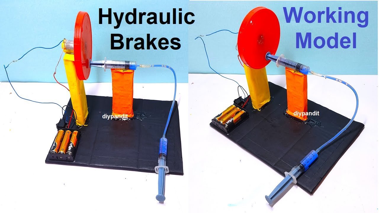
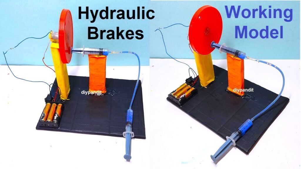
The hydraulic brake working model with a wheel, DC motor, and syringes provides a practical and visual representation of the principles behind hydraulic braking systems in vehicles.
This hands-on project enhances understanding of hydraulic pressure transmission and its application in vehicle safety systems.
Creating a hydraulic brake working model with a wheel, DC motor, and syringes involves simulating the principles of a hydraulic braking system with a rotating wheel.
Below is an explanation of how to construct and understand this model:
Materials Needed:
- DC motor with a small wheel or pulley
- Two syringes
- Plastic tubing
- Wooden base or sturdy surface
- Cardboard or foam board
- Wooden blocks or small cylinders
- Hot glue gun and glue sticks
- Small plastic containers (optional)
- Brake fluid or water
- Scissors
- Marker
Construction Steps:
- Base Construction:
- Prepare a stable base using a wooden board or any sturdy surface.
- DC Motor Mounting:
- Attach a DC motor to the base. Make sure the wheel or pulley is aligned to rotate freely.
- Syringe Mounting:
- Attach two syringes to the base using hot glue, placing them on either side of the rotating wheel.
- Plastic Tubing Connection:
- Connect plastic tubing to the nozzles of the syringes. Ensure a tight and secure connection using hot glue.
- Brake Caliper Representation:
- Cut small cardboard or foam board pieces to represent brake calipers. Attach these pieces to the end of the plastic tubing connected to the syringes.
- Piston Representation:
- Attach wooden blocks or small cylinders to the other ends of the plastic tubing to represent pistons in the brake calipers.
- Fluid Reservoirs (Optional):
- If using brake fluid, place small plastic containers near the syringes to serve as fluid reservoirs. Connect them to the plastic tubing.
- Labeling:
- Label the syringes as “Master Cylinder” and “Slave Cylinder” using a marker.
How It Works:
- DC Motor Rotation:
- When the DC motor is powered and the wheel rotates, it simulates the motion of a vehicle wheel.
- Master Cylinder (Syringe 1):
- As the wheel rotates, push the plunger of the master cylinder (syringe 1) in. This creates hydraulic pressure in the plastic tubing.
- Slave Cylinder (Syringe 2):
- The hydraulic pressure is transmitted to the slave cylinder (syringe 2), causing its plunger to move out. This simulates the action of brake fluid forcing a piston in the brake caliper to engage.
- Brake Caliper Action:
- As the pistons in the brake caliper move, they represent the squeezing action on the wheel, simulating the braking process.
- Release and Reset:
- When the master cylinder plunger is released, the hydraulic pressure decreases, allowing the brake caliper to reset to its initial position.