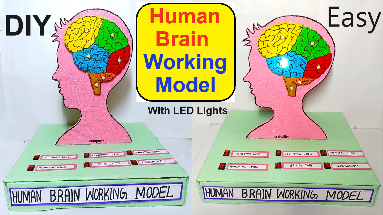
Creating a human brain working model with LED lights to showcase the different parts of the brain is a great educational project.

This model will use LEDs to illuminate specific brain regions, with switches to control each region, all powered by a 9V battery.
Here’s how you can create this model:
Materials Needed:
- Cardboard or Foam Board: To create the base and brain structure.
- Colored LED Lights: Different colors for different brain regions.
- 9V Battery: To power the LEDs.
- Battery Holder: For easy connection to the battery.
- Switches: One for each brain region you want to highlight.
- Wires: To connect the LEDs to the battery and switches.
- Resistors: To prevent the LEDs from burning out (if needed, depending on the LEDs used).
- Glue and Tape: For assembling the parts.
- Scissors or Craft Knife: For cutting the cardboard or foam board.
- Markers or Paint: For labeling and decorating the brain model.
- Soldering Kit (Optional): For more secure connections.
Step-by-Step Video Instructions:
1. Creating the Brain Structure:
- Draw the Brain Outline: On a piece of cardboard or foam board, draw an outline of the human brain, large enough to clearly label different regions.
- Cut Out the Brain: Carefully cut out the brain shape using scissors or a craft knife.
- Section the Brain: Draw lines to divide the brain into its major regions, such as the frontal lobe, parietal lobe, occipital lobe, temporal lobe, cerebellum, and brainstem.
2. Setting Up the LEDs:
- Position the LEDs: Decide where you want the LEDs to be placed to highlight each brain region. Use different colored LEDs for each region to distinguish them.
- Drill or Punch Holes: If you want the LEDs to be embedded, carefully drill or punch small holes in the cardboard where the LEDs will be inserted.
- Insert the LEDs: Place the LEDs through the holes, with the wires extending out the back of the cardboard. Secure the LEDs with glue or tape.
3. Wiring the LEDs:
- Prepare the Circuit: Connect each LED to a wire, ensuring that each LED has its own wire leading to a switch.
- Attach Resistors: If needed, solder or twist a resistor onto the positive leg (longer leg) of each LED to prevent excess current from damaging the LEDs.
- Connect to Switches: Attach the positive wire from each LED to a switch. The other side of the switch will be connected to the positive terminal of the 9V battery via the battery holder.
- Common Ground: Connect all the negative wires from the LEDs to a common ground, which will then connect to the negative terminal of the battery.
4. Mounting the Battery and Switches:
- Battery Placement: Secure the 9V battery in a holder on the back of the model, ensuring it is accessible for replacement if needed.
- Switches Placement: Mount the switches on the edge of the model or on a separate control panel next to the brain. Label each switch according to the brain region it controls.
- Final Wiring: Complete the circuit by connecting the switches to the battery. Ensure that each switch controls the corresponding LED.
5. Testing and Final Touches:
- Test the LEDs: Turn on each switch one by one to ensure that the corresponding LED lights up, highlighting the intended brain region.
- Label the Brain Parts: Use markers or printed labels to clearly mark each brain region on the model.
- Decorate the Model: You can paint or color the brain model to make it more visually appealing, matching the LED colors to the corresponding regions.
Display and Demonstration:
- Interactive Element: Allow viewers to press the switches to illuminate different parts of the brain, providing a clear visual demonstration of each region.
- Educational Explanation: Prepare a brief explanation or chart that describes the function of each brain region being highlighted.
This model effectively combines visual learning with hands-on interaction, making it a powerful educational tool for understanding the human brain’s structure and function.

