
Objective:
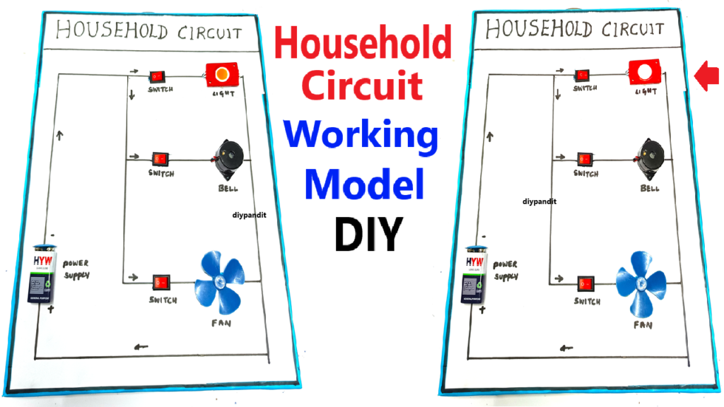
To demonstrate a simple household circuit that connects various components such as an LED light, fan, and buzzer using a 9V battery, and to show how electricity flows to power different appliances in a home. The model will be designed with color paper and cardboard for an attractive presentation.
Materials Required:
- 9V battery (for power)
- Battery holder (to secure the 9V battery)
- LED light (to demonstrate lighting in the circuit)
- Buzzer (to simulate an alarm or sound in the circuit)
- Small fan (to represent an electrical appliance)
- Switch (to control the flow of electricity)
- Connecting wires (to complete the circuit)
- Color paper and cardboard (for the base and to create appliances and labels)
- Plastic or wooden fans (small model, or an actual small fan that can be powered by a 9V battery)
- Glue, tape, and scissors (for assembly)
- Switch (to control on/off for the circuit)
Steps to Build the Household Circuit Working Model:
- Prepare the Base:
- Cut a piece of cardboard as the base for your model.
- Use color paper to decorate the base and label various parts of the circuit, such as battery, fan, LED light, buzzer, and switch.
- Set Up the Circuit:
- Battery: Place the 9V battery in the battery holder. Connect the positive and negative terminals to the rest of the circuit.
- LED Light: Attach one end of the LED light to the positive terminal of the battery and the other end to one of the switch terminals.
- Buzzer: Connect one terminal of the buzzer to the positive terminal of the battery and the other terminal to the switch.
- Fan: For the fan, connect one terminal to the negative terminal of the battery and the other terminal to the switch.
- Use wires to connect these components. The switch will allow you to control the flow of electricity to each component.
- Integrating the Switch:
- Connect a switch in the circuit between the battery and the components (fan, LED, and buzzer) to control when the devices are on or off.
- This simulates how a home switchboard controls the appliances in a household.
- Test the Circuit:
- Once all the connections are complete, test the circuit by flipping the switch. This will control whether the LED light, fan, and buzzer turn on or off.
- Fan: If using a small motorized fan, it will start spinning when the circuit is closed.
- LED Light: The LED should light up when the circuit is complete.
- Buzzer: The buzzer will make a sound when activated.
- Labeling the Model:
- Label each component with color paper or markers: Battery, LED Light, Fan, Buzzer, and Switch.
- You can use arrows or lines made from color paper to demonstrate the flow of electricity from one component to another.
How It Works:
- Battery: The 9V battery provides the electrical energy needed for the circuit.
- Switch: The switch controls the flow of electricity. When the switch is turned on, it allows current to flow through the circuit, powering the fan, LED light, and buzzer. When the switch is turned off, the flow of electricity stops, and the appliances turn off.
- LED Light: The LED lights up when the switch is on, indicating that electricity is flowing through the circuit.
- Buzzer: The buzzer emits sound when the circuit is complete and current flows.
- Fan: The fan spins when current flows through its motor, simulating the operation of a household fan.
Demonstration:
- Switching On/Off: Turn the switch on and show how the LED light illuminates, the buzzer sounds, and the fan starts spinning. This demonstrates how appliances in a household are powered by a central electrical circuit.
- Explain the Flow of Electricity: As you operate the switch, explain how electricity flows from the battery to each appliance in the household (fan, LED, buzzer) when the switch is turned on, and how it is cut off when the switch is turned off.