The purpose of creating a working model of a web server network is to demonstrate the infrastructure and functionality of a typical network used to host and deliver web services.
This model provides insights into how data is exchanged between clients and servers over the internet and the role of various components in facilitating this communication.
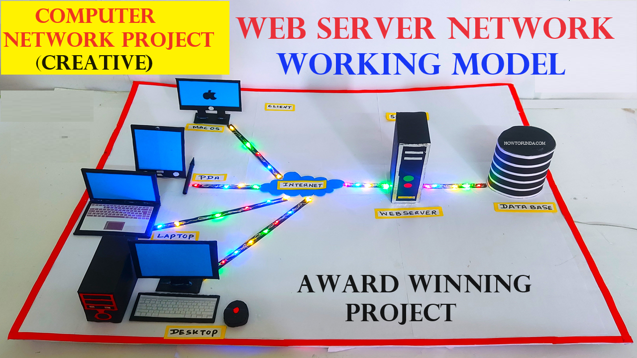
Creating a working model of a computer network with a web server, client, and server using cardboard and LED lights to showcase the network is a fascinating project for a science exhibition.

Here’s a step-by-step guide to help you build it:
Materials Needed:
- Cardboard: For creating the base, server, client, and web server models
- LED lights: To represent data transfer between the server, client, and web server
- Wires: For connecting the LED lights
- Battery: To power the LED lights
- Switches: To control the LED lights
- Resistors: To protect the LEDs from too much current
- Glue: Hot glue or strong adhesive
- Scissors/Cutter: For cutting cardboard
- Paints/Markers: For coloring and labeling the models
- Ruler: For measurements
- Breadboard: Optional, for easy wiring of the LEDs
Step by Step Video Instructions Web server network working model:
1. Prepare the Base:
- Cut a large rectangular piece of cardboard (about 18×12 inches) for the base.
- Paint or decorate the base to represent a network environment (e.g., use a network diagram with arrows to show data flow).
2. Create the Server, Client, and Web Server Models:
- Cut three rectangular boxes from cardboard to represent the server, client, and web server.
- Label each box accordingly.
- Decorate the boxes to make them look like computer servers and a client computer.
3. Position the Models on the Base:
- Place the server, client, and web server models on the base. Arrange them in a way that they form a triangle, allowing easy visualization of data transfer between them.
4. Set Up the LED Lights:
- Choose different colored LEDs to represent different types of data transfer (e.g., green for requests, red for responses).
- Insert LEDs into the cardboard boxes to represent the connection points. Use a small piece of cardboard to hold the LEDs in place if necessary.
5. Wiring the LEDs:
- Connect the LEDs using wires. Ensure each LED has a resistor to prevent it from burning out.
- Connect the positive (anode) leg of each LED to the battery’s positive terminal through a switch.
- Connect the negative (cathode) leg of each LED to the battery’s negative terminal.
- You can use a breadboard for easier wiring and to keep the connections organized.
6. Create the Network Connections:
- Use wires to represent the network cables. Connect one end of a wire to the server and the other end to the client. Repeat this for the server to the web server and the client to the web server.
- Secure the wires on the base using glue or tape, ensuring they are neatly arranged.
7. Adding Switches:
- Place switches on the base near each box to control the LEDs. This will simulate the data transfer process when the switches are turned on and off.
- Label the switches (e.g., “Send Request”, “Receive Response”).
8. Final Assembly:
- Make sure all connections are secure and the LEDs light up when the switches are turned on.
- Test the circuit to ensure it works correctly. Press the switches to simulate data transfer between the server, client, and web server.
9. Decoration and Labeling:
- Use markers and paints to label the different parts of the network.
- Add arrows and labels on the base to indicate the flow of data.
- Decorate the cardboard boxes to resemble actual network devices.