A computer flowchart is a diagrammatic representation of a process or algorithm using symbols and arrows to show the flow of control. It is used in programming and system design to visually map out logical steps in solving a problem.
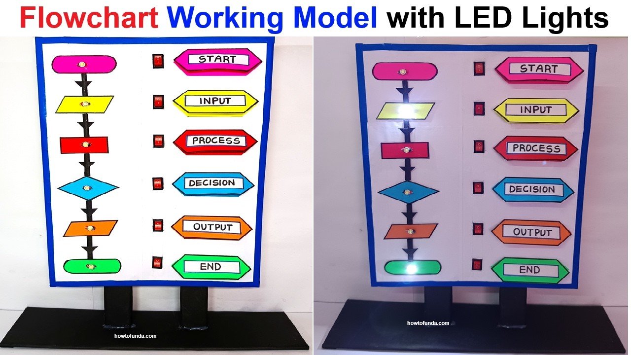
This working model will visually represent a computer flowchart with LED lights and switches, allowing interaction by turning on LEDs step by step as the process flows.

Materials Required
Cardboard – For base and structure
Color paper – For designing flowchart shapes
LED lights (various colors) – To illuminate each step
9V battery – Power source
Switches (one for each flowchart shape) – To control flow
Wires – For electrical connections
Resistors (if needed for LED safety)
Nails or conductive materials – For circuit connections
Glue, tape, and scissors – For assembly
Markers/Pens – For labeling
Step-by-Step Process to Build the Model
Step 1: Design the Flowchart Layout
- Cut flowchart shapes from color paper:
- Oval → Start/End
- Rectangle → Process
- Diamond → Decision
- Parallelogram → Input/Output
- Arrange them on the cardboard base and paste them neatly.
Step 2: Install LED Lights in Each Shape
- Place an LED in each shape to indicate activation.
- Use different LED colors to represent steps (Green for Start, Red for End, Blue for Process, Yellow for Decision).
Step 3: Wire the Circuit with Switches
- Connect each LED to a separate switch.
- Create a series circuit where pressing a switch activates the next step.
- Use a 9V battery to power the LEDs.
- Ensure proper connections with wires and nails for smooth flow.
Step 5: Add Labels and Arrows
- Use a marker to draw arrows between shapes.