
Introduction
In the realm of urban planning and energy conservation, the efficient use of street lighting plays a pivotal role. Traditional systems often rely on manual controls or timers, leading to unnecessary energy consumption.
The quest for sustainability and efficiency has spurred the development of automatic street lighting solutions, driven by advanced technologies.
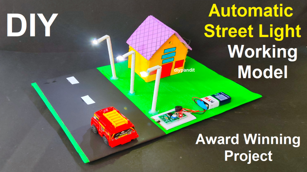
The “Automatic Street Light Working Model” project stands at the intersection of science, engineering, and environmental consciousness. Through the integration of LED lights and an infrared sensor, this model exemplifies a smart and energy-efficient approach to urban lighting.
Creating an automatic street light working model for a science project using LED lights, an infrared sensor, and cardboard is an excellent way to understand how modern street lighting systems work. Follow these steps to build your model:
Materials Needed:
- Cardboard sheets (for structure)
- LED lights
- Infrared (IR) sensor module
- Wires and soldering equipment (or breadboard and jumper wires)
- Resistors (if required by the IR sensor)
- Battery or power source
- Switch (optional)
- Glue, tape, scissors, and a cutter
- Small reflectors (optional, for enhanced light direction)
Steps:
- Design the Street Light Structure:
- Draw and cut out the shape of a street light post and the top part where the LED lights will be attached from the cardboard.
- Mount the LED Lights:
- Attach the LED lights to the top part of the street light structure. Space them out evenly to provide adequate light coverage.
- Install the IR Sensor:
- Determine the best location on the street light post to mount the IR sensor. This should be in a position where it can effectively detect movement.
- Wire the Circuit:
- Connect the components as follows:
- Connect the positive terminals of the LED lights to the positive terminal of the power source.
- Connect the negative terminals of the LED lights to the output terminals of the IR sensor.
- Connect the power source to the input terminals of the IR sensor.
- If required by the IR sensor, connect the appropriate resistors.
- Connect the components as follows:
- Position the Reflectors (Optional):
- Attach small reflectors around the LED lights to direct the light downwards, simulating street lighting.
- Set Up the Power Source:
- Connect the battery or power source to the circuit.
- Test the Model:
- Power on the circuit and observe how the LED lights respond to movement detected by the IR sensor. The lights should turn on when motion is detected and turn off after a set period.
- Optional: Add a Switch (for manual control)
- If desired, you can include a switch in the circuit to manually control the lights.
- Assemble and Decorate:
- Securely attach all components to the cardboard structure using glue, tape, or any appropriate fasteners. Add any additional decorative elements.
- Fine-Tune and Demonstrate:
- Adjust the sensitivity and delay settings on the IR sensor if available. This can affect how quickly the lights respond to motion.
- Explain the Science:
- In your project presentation, explain how the IR sensor works by detecting heat signatures and how it triggers the LED lights to turn on. Discuss the importance of automatic street lights in energy conservation.
This project effectively demonstrates the practical application of an automatic street lighting system and allows for a deeper understanding of how infrared sensors work in real-world scenarios.