
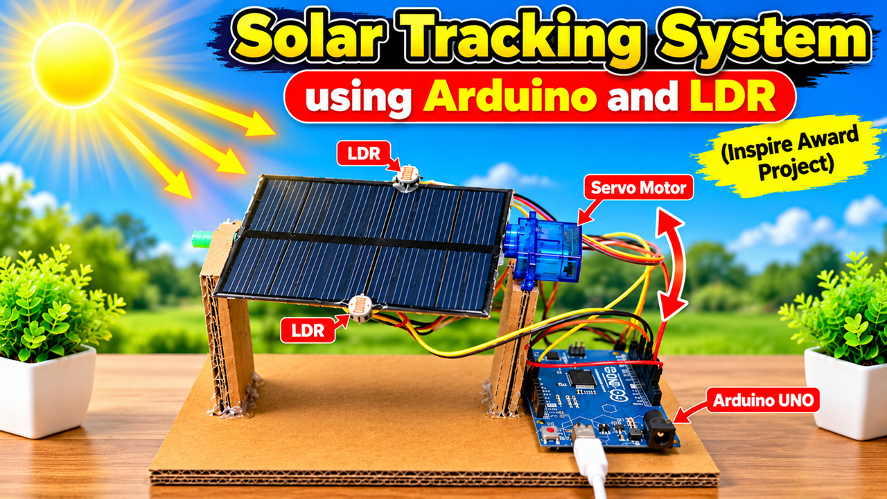
1. Introduction
Good morning, respected judges, teachers, and my dear friends.
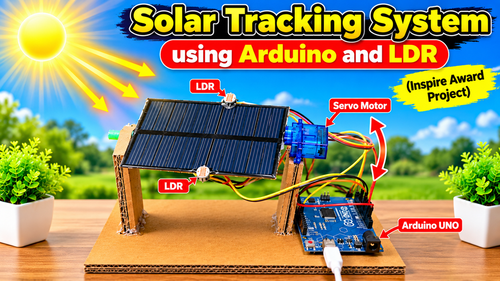
Today, I am going to present my science project, “Solar Tracking System Using Arduino and LDR.”
Solar energy is a clean and renewable source of energy. Solar panels convert sunlight into electrical energy. However, the position of the Sun changes throughout the day, and a fixed solar panel may not always face the direction that receives the strongest sunlight.
My project demonstrates an automatic solar tracking system that adjusts the position of a solar panel according to the direction of light. It uses Light Dependent Resistors (LDRs), an Arduino UNO, and a servo motor to help the panel face the brighter side.
2. Aim of the Project
The main objectives of this project are:
- To demonstrate automatic solar panel movement.
- To understand how LDR sensors detect light intensity.
- To learn how Arduino processes sensor readings.
- To demonstrate the use of a servo motor for controlled movement.
- To explore ways of improving the orientation of solar panels.
3. Materials Required
The following materials are required:
- Arduino UNO board.
- Two LDR sensors.
- Two resistors, typically around 10 kΩ, for the LDR voltage-divider circuits.
- One servo motor suitable for the panel’s weight.
- Small solar panel or lightweight demonstration panel.
- Breadboard and jumper wires.
- USB cable or suitable regulated power supply.
- Cardboard sheets for the base and support frame.
- Glue, scissors, ruler, and insulating tape.
- Optional multimeter for testing voltage and connections.
Choose a servo motor with sufficient torque for the panel. The solar panel should be lightweight, and the power supply must be suitable for the Arduino and servo.
4. Making Process
Step 1: Prepare the base
Take a thick cardboard sheet and cut it into a rectangular base. Reinforce it with extra cardboard layers so it can support the solar panel, servo motor, and Arduino board.
Step 2: Build the support frame
Cut cardboard strips to make two vertical supports. Attach them firmly to the base. Create a lightweight mounting bracket that allows the panel to rotate. Ensure that the structure moves freely without wobbling.
Step 3: Mount the solar panel
Attach the solar panel to the rotating bracket. Connect its output terminals to a multimeter if you want to demonstrate the voltage generated by the panel. Keep the panel’s electrical output separate from the Arduino input unless a suitable interface circuit is provided.
Step 4: Install the LDR sensors
Place one LDR on the left side of the panel and the other on the right side. Add a small vertical divider between them to create a light difference when the light source is not centred. This helps the sensors detect which side receives more light.
Step 5: Connect the LDR circuits
Connect each LDR with a resistor to form a voltage-divider circuit. Connect the midpoint of each divider to a separate Arduino analog input, such as A0 and A1. The Arduino reads the voltages and compares the light levels.
Step 6: Connect the servo motor
Connect the servo’s signal wire to a suitable Arduino digital pin, such as pin 9. Connect its power and ground according to the servo manufacturer’s specifications. The Arduino and servo supply must share a common ground.
A separate regulated supply may be needed because some servos draw more current than the Arduino board can safely provide.
Step 7: Upload the Arduino program
Write or upload a program that reads both LDR values, compares them, and commands the servo to move toward the brighter side. Include a small tolerance range to avoid unnecessary movement when both sensors receive nearly equal light.
Step 8: Test and decorate
Power the system and shine a torch on the left and right LDR sensors in turn. Check whether the panel moves in the intended direction. Adjust the sensor positions and program if necessary. Finally, secure the wires and decorate the model with labels.
5. Working Principle
The working principle is based on light detection, sensor comparison, and automatic motor control.
An LDR is a resistor whose resistance changes according to the amount of light falling on it. In general, its resistance decreases as light intensity increases.
The two LDR circuits produce voltage readings that the Arduino UNO reads through its analog inputs. The program compares the readings to estimate which side receives more light.
If the left LDR detects stronger light than the right LDR, the Arduino commands the servo motor to turn the panel toward the left. If the right LDR receives stronger light, the panel turns toward the right.
When both sensors receive nearly equal light, the program keeps the panel approximately in its current position. This process repeats while the system is operating.
6. Demonstration at the Exhibition
During the exhibition, I will first explain the solar panel, two LDR sensors, Arduino UNO, and servo motor.
Next, I will shine a torch toward the left LDR. The Arduino will compare the readings and move the panel toward the brighter side.
Then, I will move the torch toward the right LDR. The panel should adjust in the opposite direction.
Finally, I will place the torch between the two sensors. When both sensors receive similar light, the panel should remain approximately centred.
This demonstration shows how a sensor-based control system can automatically adjust the position of a solar panel.
7. Advantages and Applications
The main advantages of this project are:
- Demonstrates automatic adjustment of a solar panel.
- Introduces students to sensors, programming, and robotics.
- Shows how light intensity can be measured electronically.
- Can help a panel maintain a favourable orientation under suitable conditions.
- Can be adapted for solar research projects and educational demonstrations.
Solar tracking may improve energy collection compared with a fixed panel in some installations, but the actual benefit depends on weather, location, tracking energy use, mechanical losses, and system design.
8. Conclusion
To conclude, my Solar Tracking System demonstrates how Arduino, LDR sensors, and a servo motor can work together to adjust a solar panel according to light intensity.
Through this project, I learned about renewable energy, sensor circuits, microcontroller programming, and automatic control systems.
My message is: “Follow the Light, Harness Solar Energy, and Build a Sustainable Future.”
Thank you, everyone!
Learn, Create, and Innovate!