
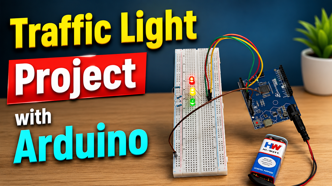
A Traffic Light Project with Arduino is a simple, attractive, and educational working model for a school science exhibition. It demonstrates how electronic circuits, LEDs, programming, and automatic timing can be combined to simulate a real traffic signal system.
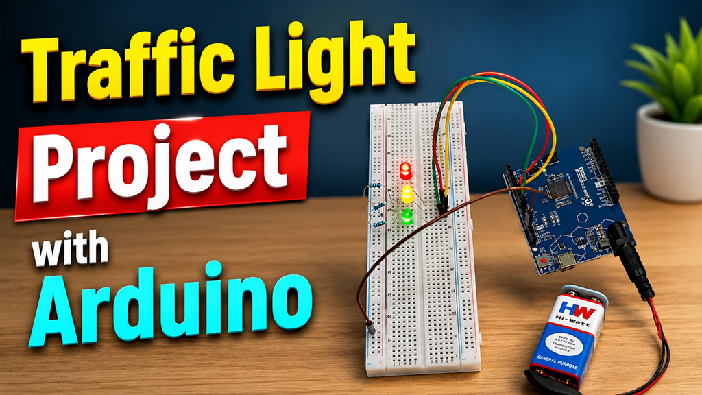
Traffic lights play an important role in controlling vehicles and pedestrians at road intersections. The familiar red, yellow, and green lights communicate when road users should stop, prepare, or proceed. In this DIY project, an Arduino Uno acts as the controller and automatically changes the three LEDs according to a programmed sequence. Arduino-based traffic-light projects are commonly used to introduce students to digital outputs, programming, loops, and timing.
Introduction
The main objective of this project is to create a miniature automatic traffic signal using inexpensive electronic components and easily available craft materials.
Instead of manually switching each LED on and off, the Arduino is programmed to control the lights automatically. The red, yellow, and green LEDs are connected to different digital pins of the Arduino. When the program runs, the Arduino sends electrical signals to these pins, causing the LEDs to glow in a predetermined sequence.
For example:
Red → Green → Yellow → Red
The timing can be changed in the program according to the requirements of the demonstration.
This makes the project especially useful for a science exhibition because visitors can actually see the concept of automation and programmed control in action.
Materials Required
For a basic Arduino traffic light model, you will need:
- Arduino Uno
- Breadboard
- Red LED
- Yellow LED
- Green LED
- 3 × 220Ω or 330Ω resistors
- Jumper wires
- USB cable
- Cardboard or thermocol for the model
- Black chart paper
- Glue
- Scissors
- Toy cars
- White chart paper for road markings
A resistor should be used with each LED to limit current and protect the LED. Educational Arduino traffic-light examples commonly use LEDs, resistors, jumper wires, and an Arduino board.
How to Make the Traffic Light Model
Step 1: Prepare the Base
Take a thick cardboard sheet and use it as the base of the project.
Cover the surface with black chart paper to represent a road. Use white strips to create:
- Lane markings
- Zebra crossings
- Stop lines
- Road dividers
You can add small toy cars, houses, trees, and pedestrians to make the model more attractive.
A realistic road layout helps visitors immediately understand what the traffic signal is controlling.
Step 2: Make the Traffic Signal
Take a rectangular piece of cardboard and create a small traffic-light housing.
Make three circular holes vertically:
- Red – top
- Yellow – middle
- Green – bottom
Insert the corresponding LEDs into the holes.
Cover the surrounding area with black chart paper so that the LEDs stand out clearly.
Attach the signal box to a cardboard or wooden pole and fix it to the base.
Arduino Circuit Connections
For a simple version, use:
| Component | Arduino Pin |
|---|---|
| Red LED | D8 |
| Yellow LED | D9 |
| Green LED | D10 |
| LED negative terminals | GND |
Connect each LED through its own resistor.
For example:
D8 → 220Ω resistor → Red LED → GND
D9 → 220Ω resistor → Yellow LED → GND
D10 → 220Ω resistor → Green LED → GND
Make sure the LED polarity is correct. The longer leg is normally the positive/anode connection, while the shorter leg is the negative/cathode connection.
The Arduino Uno acts as the brain of the project, controlling the LEDs through its digital output pins.
Arduino Program
The following simple program automatically operates the three traffic lights:
int redLED = 8;
int yellowLED = 9;
int greenLED = 10;

void setup() {
  pinMode(redLED, OUTPUT);
  pinMode(yellowLED, OUTPUT);
  pinMode(greenLED, OUTPUT);
}

void loop() {

  // RED - STOP
  digitalWrite(redLED, HIGH);
  digitalWrite(yellowLED, LOW);
  digitalWrite(greenLED, LOW);
  delay(5000);

  // GREEN - GO
  digitalWrite(redLED, LOW);
  digitalWrite(yellowLED, LOW);
  digitalWrite(greenLED, HIGH);
  delay(5000);

  // YELLOW - WAIT
  digitalWrite(redLED, LOW);
  digitalWrite(yellowLED, HIGH);
  digitalWrite(greenLED, LOW);
  delay(2000);
}
Arduino traffic-light examples use the same basic principle: configuring LED pins as outputs and switching them HIGH or LOW according to programmed timing.
How Does the Project Work?
The working principle is based on digital output control and timing.
When the Arduino is powered on, it executes the instructions inside the loop() function repeatedly.
1. Red Light
First, the Arduino switches the red LED ON.
The yellow and green LEDs remain OFF.
Meaning: STOP
The model waits for five seconds.
2. Green Light
After five seconds, the Arduino switches the red LED OFF and turns the green LED ON.
Meaning: GO
The green light remains ON for five seconds.
3. Yellow Light
The Arduino then switches the green LED OFF and turns the yellow LED ON.
Meaning: WAIT / GET READY
The yellow LED remains ON for two seconds.
After that, the program returns to the red-light stage and the entire cycle repeats.
Therefore, the model continuously demonstrates:
STOP → GO → WAIT → STOP
Science Behind the Project
This project combines several important science and technology concepts.
Electrical Circuit
Electric current flows through a complete circuit. When the Arduino output pin is activated, current flows through the LED and resistor, causing the LED to illuminate.
LED
LED stands for Light Emitting Diode. It produces light when current passes through it in the correct direction.
Resistor
The resistor limits the current flowing through the LED and helps prevent the LED from being damaged.
Microcontroller
The Arduino contains a microcontroller that executes the program and controls the connected electronic components.
Programming
The program uses commands such as:
pinMode()– defines a pin as an input or output.digitalWrite()– switches an output HIGH or LOW.delay()– pauses the program for a specified amount of time.
Together, these commands allow the student to create an automatic sequence.
Why Use Arduino?
A traditional traffic-light model can be operated manually using switches. However, Arduino makes the project automatic and programmable.
The biggest advantage is that the timing can easily be changed.
For example:
- Red = 10 seconds
- Green = 8 seconds
- Yellow = 3 seconds
The student only needs to modify the values in the program.
Arduino traffic-light projects are therefore useful for demonstrating the connection between hardware and software.
Applications
The model can be connected to several real-world applications, including:
- Road traffic management
- Pedestrian crossings
- Railway crossing simulations
- Smart-city projects
- Automatic street systems
- Vehicle management
- Robotics and automation
- Embedded-system learning
Real traffic systems can be much more sophisticated than this school model, using sensors, controllers, pedestrian signals, coordinated intersections, and other technologies.