Creating a working model to demonstrate the concept of squares in mathematics with an interactive “match the following” board using nails, LED lights, and wires can be both educational and engaging.

Here’s a step-by-step guide:
Materials Needed:
- Large piece of cardboard (about 60 cm x 40 cm)
- Colored paper
- Scissors
- Glue
- Ruler
- Marker
- Small nails or brass fasteners
- Insulated wire
- LEDs (one for each match)
- Battery holder and batteries
- Electrical tape
- Soldering iron and solder (optional, for secure connections)
Steps by Steps Video Instructions:
1. Prepare the Base Board:
- Cut the Cardboard Base: Cut a large rectangular piece of cardboard to serve as the base.
- Cover with Colored Paper: Cover the cardboard base with colored paper using glue to make it visually appealing.
2. Create the Sections:
- Divide into Two Sections: Divide the board into two sections: one for the numbers and one for the corresponding squares.
- Label the Sections: On the left side, write the numbers (e.g., 1, 2, 3, 4, 5, 6, 7, 8, 9, 10). On the right side, write the corresponding squares (e.g., 1, 4, 9, 16, 25, 36, 49, 64, 81, 100).
- Place the Nails/Brass Fasteners: Insert small nails or brass fasteners next to each number and its corresponding square. Ensure they are firmly in place and protrude slightly from the surface.
3. Set Up the Electrical Circuit:
- Plan the Circuit: Plan a simple circuit where each correct match will light up an LED.
- Connect Wires to Nails/Fasteners: Connect a wire to each nail or fastener on the left side (numbers) and its corresponding pair on the right side (squares). Use electrical tape to secure the wires if needed.
- Connect LEDs:
- Connect an LED between each pair of wires. The longer leg (anode) of the LED should connect to the positive side of the battery, and the shorter leg (cathode) to the negative side.
- Power Source: Connect all the positive wires from the LEDs to the positive terminal of the battery holder. Connect all the negative wires to the negative terminal of the battery holder.
- Secure Connections: Use electrical tape or soldering to ensure all connections are secure and won’t come loose.
4. Test the Circuit:
- Insert Batteries: Place the batteries in the holder and test each pair to ensure the LED lights up when a correct match is made.
- Troubleshoot: If any LED doesn’t work, check all connections and ensure the polarity is correct.
5. Final Assembly:
- Decorate: Add additional decorations, borders, or patterns to make the board more attractive.
- Instructions: Include a brief set of instructions on how to use the board, if necessary.
- Stability: Ensure all parts are securely attached and the model is stable.
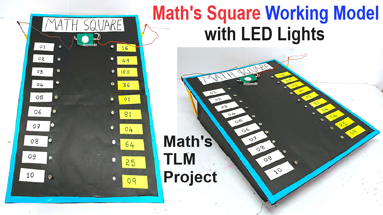
Visual Layout:
- Imagine the cardboard base divided into two vertical sections.
- The left section lists the numbers 1 to 10.
- The right section lists the corresponding squares (1, 4, 9, 16, 25, 36, 49, 64, 81, 100).
- Each correct match completes a circuit and lights up an LED.
Example Wiring for a Single Pair:
- Number 3:
- Nail on the left side labeled “3”.
- Wire from this nail to one leg of an LED.
- Square 9:
- Nail on the right side labeled “9”.
- Wire from the other leg of the LED to this nail.
This project will help students learn the concept of squares in an interactive way, making it an excellent educational tool for a classroom or exhibition.