
Aim / Objective:
To demonstrate how a two-way switch can control the operation of electrical devices like LED lights or a DC motor from two different locations.
Materials Required:
- 2 LED lights
- 1 DC motor (small)
- 2-way switch (SPDT – Single Pole Double Throw)
- Battery (9V or 6V)
- Connecting wires
- Resistor (220Ω–470Ω for LED protection)
- Breadboard or cardboard base
- Tape or glue
Working Principle:
A two-way switch allows control of a circuit from two different points.
- The switch alternates the connection between two terminals, directing the current either to turn ON or OFF a device.
- In this model:
- The LEDs light up depending on the switch position.
- The DC motor can rotate in response to the switch connections.
- It demonstrates basic concepts of current flow, switch control, and circuit design.
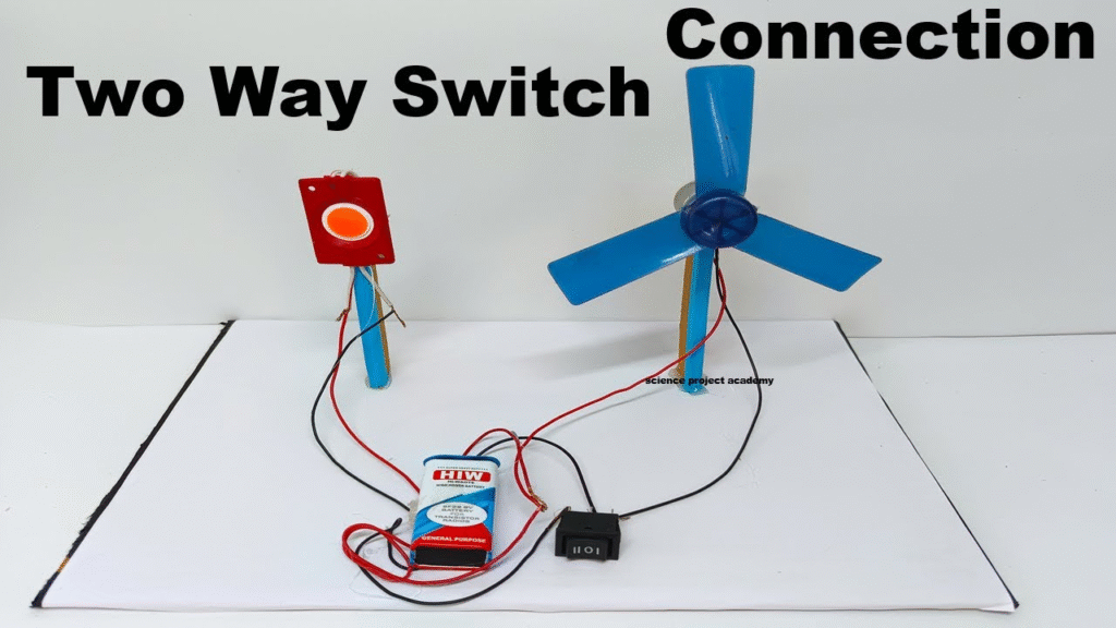
Procedure:
- Mount the LEDs and DC motor on a breadboard or cardboard base.
- Connect the battery to the switch circuit using wires.
- Connect the SPDT two-way switch so that flipping it directs current either to the LED or the motor.
- Include a resistor in series with LEDs to prevent burning.
- Flip the switch from one position to another and observe how:
- The LED turns ON/OFF.
- The DC motor starts/stops depending on the switch position.
- Demonstrate controlling the devices from two different points if using two switches connected in a real two-way wiring setup.
Observation:
- Flipping the switch changes the circuit path, controlling which device receives current.
- The LED lights up or the motor rotates based on switch position.
- This clearly demonstrates the working of a two-way switching system.
Conclusion:
The model shows how two-way switches allow electrical devices to be controlled from two locations efficiently.
It is useful in real-life applications such as staircase lights, hallways, or multiple control points for devices, demonstrating basic electrical circuit control and safety principles.