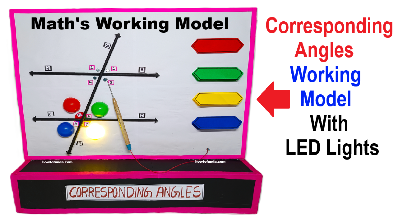
This model shows corresponding angles. When a transversal cuts two parallel lines, angles in the same position form corresponding pairs.
Here, nails act as touch points. When I touch nail 1 and nail 5 together, the circuit completes and the LED glows. That means ∠1 and ∠5 are corresponding angles.

Materials Needed
Board & Structure
- Thick chart board / foam board / cardboard
- Scale, pencil, markers
- Metal nails (4 nails for 4 angles)
Electrical Items
- LEDs (4 LEDs for 4 pairs of corresponding angles)
- Copper wire (thin)
- 9V battery or 5V power bank
- Battery clip
- Conductive tape (optional)
- Small switch (optional)
- Hot glue / fevicol
Prepare the cardboard setup
- two parallel lines on the board using color paper
- one transversal cutting both lines using color paper .
- You will get 8 angles.
- Label them clearly: 1,2,3,4 at top intersection and 5,6,7,8 at bottom.
Fixing the Metal Nails
- Hammer one small metal nail at the vertex of each angle (1,2,3,4) (total 4).
- Ensure nail head is exposed so it can be touched by metal probe to close the circuit.
- Nails must not touch each other (avoid short circuits).
These nails will act as touch sensors.
Wiring the LEDs (Touch-to-Glow Logic)
Concept
You will create simple circuits where:
- Touching one nail completes connection → current flows → LED lights.
For each Corresponding Angle pair:
Pairs are:
1 ↔ 5
2 ↔ 6
3 ↔ 7
4 ↔ 8
How the Model Works (Simple Explanation for Students)
- Metal nails act as touch sensors.
- When you touch one corresponding angles, using metal probe.
- The circuit gets closed → LED turns ON.
- This shows the two angles are corresponding angles.