Introduction
Understanding coordinate geometry is a very important part of mathematics. One of the first concepts students learn in coordinate geometry is the Cartesian coordinate system and the idea of quadrants. Many students find it difficult to imagine how a point belongs to a particular quadrant just by looking at its x-value and y-value.

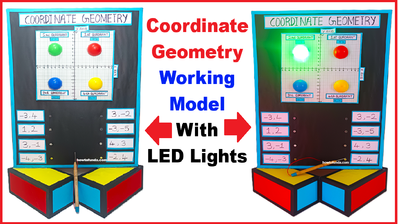
To make this concept easy, interesting, and practical, this working model has been designed. This model helps students visually and interactively understand which quadrant a coordinate point belongs to. When a coordinate is selected using a probe, the correct quadrant LED glows automatically, making learning simple, fun, and memorable.
Aim of the Model
The main aim of this model is to:
- Help students understand quadrants in coordinate geometry
- Show how positive and negative values of x and y decide the quadrant
- Provide a hands-on learning experience
- Make learning mathematics interactive and engaging
Basic Concept Used
This model is based on the Cartesian Coordinate System, which consists of:
- X-axis (horizontal line)
- Y-axis (vertical line)
These two axes divide the plane into four regions, called quadrants:
- Quadrant I
- Quadrant II
- Quadrant III
- Quadrant IV
Each quadrant has a fixed sign pattern for x and y values.
Quadrants and Their Sign Rules
| Quadrant | x-value | y-value |
|---|---|---|
| Quadrant I | Positive (+) | Positive (+) |
| Quadrant II | Negative (–) | Positive (+) |
| Quadrant III | Negative (–) | Negative (–) |
| Quadrant IV | Positive (+) | Negative (–) |
This model demonstrates these rules practically using LEDs.
Components of the Model
The model consists of the following main parts:
- Base Board
- A square board showing the X-axis and Y-axis
- Divided clearly into four quadrants
- Coordinate Nails
- Small metal nails fixed at different points on the board
- Each nail represents a coordinate point such as:
- (3, 4)
- (–2, 5)
- (–4, –3)
- (5, –2)
- Probe
- A metal probe connected to the circuit
- Used to touch the selected coordinate nail
- LED Lights
- Four LEDs labeled:
- Quadrant I
- Quadrant II
- Quadrant III
- Quadrant IV
- Only one LED glows at a time
- Four LEDs labeled:
- Electrical Circuit
- Hidden behind the board
- Connects each nail to the correct quadrant LED
How the Model Works (Step-by-Step Explanation)
Step 1: Representation of Coordinates
Each nail on the board represents a specific coordinate point. For example:
- A nail in the first quadrant represents a point like (3, 4)
- A nail in the second quadrant represents a point like (–2, 5)
- A nail in the third quadrant represents a point like (–4, –3)
- A nail in the fourth quadrant represents a point like (5, –2)
The position of the nail itself visually shows where the point lies on the graph.
Step 2: Understanding the Signs of x and y
Before touching the nail, students are encouraged to observe:
- Is the point to the right or left of the Y-axis?
- Right → x is positive
- Left → x is negative
- Is the point above or below the X-axis?
- Above → y is positive
- Below → y is negative
This helps students think logically before checking the answer.
Step 3: Touching the Nail with the Probe
When the student touches a coordinate nail with the probe:
- The electrical circuit gets completed
- Current flows through the predefined path
- The LED of the correct quadrant lights up
For example:
- Touching a nail representing (3, 4) will glow the Quadrant I LED
- Touching a nail representing (–2, 5) will glow the Quadrant II LED
Step 4: LED Glowing Automatically
The glowing LED gives instant feedback:
- If the student’s understanding is correct, the expected LED glows
- If not, the glowing LED helps them realize their mistake
This immediate response helps in self-learning and error correction.
Explanation of Each Quadrant Using the Model
Quadrant I (Positive x, Positive y)
- Points lie to the right of the Y-axis and above the X-axis
- Example: (2, 3), (5, 4)
- When such a nail is touched, the Quadrant I LED glows
Quadrant II (Negative x, Positive y)
- Points lie to the left of the Y-axis and above the X-axis
- Example: (–3, 4), (–1, 6)
- Touching the nail lights up the Quadrant II LED
Quadrant III (Negative x, Negative y)
- Points lie to the left of the Y-axis and below the X-axis
- Example: (–4, –2), (–5, –6)
- The Quadrant III LED glows
Quadrant IV (Positive x, Negative y)
- Points lie to the right of the Y-axis and below the X-axis
- Example: (4, –3), (6, –1)
- The Quadrant IV LED glows
Conclusion
This working model is a simple yet powerful tool to understand quadrants in coordinate geometry. By combining visual placement, physical interaction, and instant LED feedback, it transforms a theoretical topic into an engaging learning experience.
The model not only helps students identify the correct quadrant but also strengthens their overall understanding of coordinates, signs, and graph interpretation.