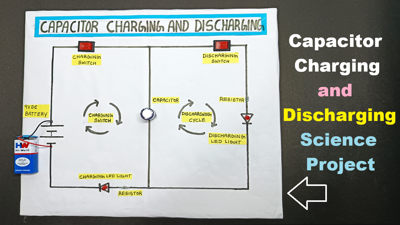
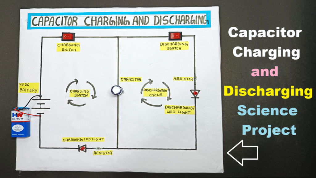
In this physics project, we demonstrate the charging and discharging process of a capacitor using simple components like a capacitor, resistor, LED lights, and two switches.
This model helps students visualize how energy is stored and released in electronic circuits — one of the most important concepts in physics and electronics.
What You’ll Learn:
- How a capacitor stores electrical energy (charging)
- How it releases energy through a resistor and LED (discharging)
- How to use two switches for manual control of charge/discharge
- Practical demonstration using LED brightness
Materials Used:
- 1 × Capacitor (e.g., 1000µF, 25V)
- 1 × Resistor (1kΩ to 10kΩ)
- 1 × LED
- 2 × Switches (for charging and discharging)
- 1 × 9V Battery
- Breadboard / Wires
Working Principle:
When you press the charging switch, current flows from the battery through the resistor to the capacitor, causing the LED to glow as it charges.
When the discharging switch is pressed, the stored energy in the capacitor flows through the LED, showing a gradual dimming effect as the capacitor releases energy.
STEPS TO BUILD
Step 1: Prepare the Base
- Take a cardboard or wooden board and mark places for battery, switches, resistor, capacitor, and LED.
- Fix components neatly using a glue gun or tape.
- Label them: Battery, Resistor, Capacitor, Switch 1 (Charge), Switch 2 (Discharge), LED.
Step 2: Connect the Resistor and Capacitor
- Connect one end of the resistor to Switch 1 (charging switch).
- Connect the other end of the resistor to the positive leg (+) of the capacitor.
- Connect the negative leg (–) of the capacitor to battery negative (ground).
Step 3: Connect the LED for Discharging
- Connect the positive leg of the LED to the positive leg of the capacitor.
- Connect the negative leg of the LED to Switch 2 (discharging switch).
- Connect the other terminal of Switch 2 to battery negative (ground).
Step 4: Connect the Power Supply
- Connect the 9V battery positive to Switch 1 input terminal.
- Connect the battery negative to common ground for capacitor and LED.
Step 5: Testing the Circuit
- Press Switch 1 (Charging):
- The capacitor charges through the resistor.
- The LED may glow faintly as charging happens.
- Release Switch 1 and Press Switch 2 (Discharging):
- The stored energy in the capacitor flows through the LED.
- The LED glows brightly at first, then dims slowly — showing discharge.