
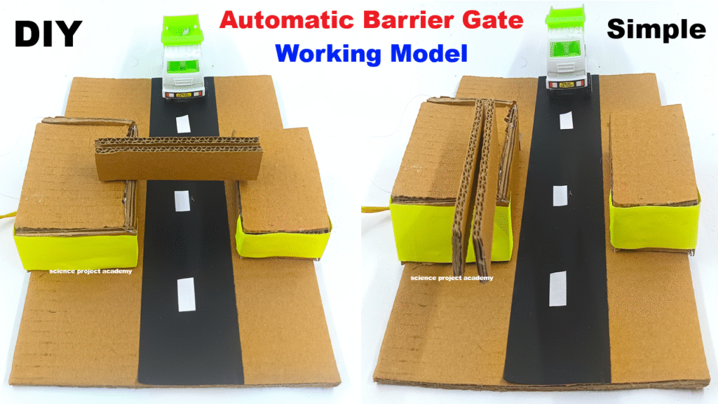
An automatic barrier gate operates using a DC motor and a rotating arm, controlled manually or with sensors. It’s used to restrict or allow vehicle access in areas like parking zones or railway crossings.
This model shows how an automatic barrier gate works using a DC motor to control the movement of the gate arm. These gates are common in parking lots, railway crossings, and toll booths. It demonstrates automation, electric motor usage, and mechanical control systems.
Materials Required:
- Cardboard (for base, booth, and gate arm)
- DC motor (3V–9V)
- Switch
- 9V battery + connector
- Wooden stick or straw (for rotating axis)
- Glue gun or Fevicol
- Woolen thread (optional for support)
- Wires
- Color paper and markers (for decoration)
Video Step-by-Step Instructions:
1. Prepare the Base and Booth:
- Cut and glue a strong cardboard base.
- Create a small cardboard booth or box on one side (acts as the motor housing).
2. Create the Barrier Arm:
- Cut a long rectangular strip of cardboard (the gate arm).
- Decorate with red & white stripes for realism.
- Attach the arm to the DC motor shaft or to a wooden stick connected to the motor using a wheel or gear.
3. Install the Motor Mechanism:
- Place the DC motor inside the booth.
- Mount the barrier arm securely on the rotating shaft.
- When powered, the shaft rotates and lifts/lowers the gate.
4. Connect the Electrical Circuit:
- Connect the DC motor to a 9V battery through a switch.
- Press the switch → motor rotates → barrier rises or lowers.
- Optional: Use double-pole switch or reverse polarity switch to open and close the gate.