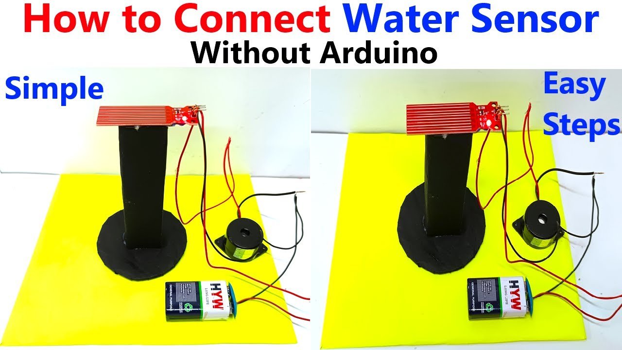
Connecting a water sensor or rain sensor without using an Arduino is a straightforward project that can be accomplished with basic electronic components.

Below is a step-by-step guide to create a simple circuit using a water sensor, a 9V battery, a relay, and an indicator (like an LED or a buzzer).
Components Needed:
- Water Sensor/Rain Sensor Module (can be a simple conductive water sensor)
- 9V Battery (with battery connector)
- Relay Module (5V relay is common, but ensure it can handle the load you plan to use)
- LED (or buzzer as an indicator)
- 220Ω Resistor (for the LED)
- Jumper Wires (for connections)
- Breadboard (optional, for easier connections)
- Switch (optional, for manually turning the circuit on/off)
Step-by-Step Instructions:
1. Understand the Water Sensor:
- A typical water sensor consists of two conductive traces that form a sensor pad. When water bridges these traces, it completes the circuit, signaling a high (or low) output.
- The output can be either digital (on/off) or analog (varying resistance depending on water level). For simplicity, we will use a basic digital water sensor.
2. Prepare the Relay:
- The relay will act as a switch to control higher voltage devices (like a pump or buzzer) using the output from the water sensor.
- Identify the relay’s pins:
- Common (COM): Connects to the power supply of the device you want to control.
- Normally Open (NO): Connects to the device (it closes the circuit when activated).
- Normally Closed (NC): This is not used in our basic setup.
3. Connect the Water Sensor:
- Power the Sensor:
- Connect the VCC (power) pin of the water sensor to the positive terminal of the 9V battery.
- Connect the GND (ground) pin of the water sensor to the negative terminal of the 9V battery.
- Connect the Output:
- Connect the output pin of the water sensor to one terminal of the relay coil. This is typically marked as IN or something similar.
4. Set Up the Relay:
- Connect the Relay Coil:
- Connect the other terminal of the relay coil to the negative terminal of the battery (GND).
- Connect the Load (LED/Buzzer):
- For an LED:
- Connect the LED’s anode (+) to the COM pin of the relay.
- Connect a 220Ω resistor from the LED’s cathode (-) to the negative terminal of the battery.
- For a Buzzer:
- Connect one terminal of the buzzer to the COM pin of the relay.
- Connect the other terminal of the buzzer to the negative terminal of the battery.
- For an LED:
5. Make the Final Connections:
- Ensure all connections are secure and correctly aligned:
- The sensor’s power connections to the battery (VCC to positive, GND to negative).
- The output of the sensor to the relay.
- The relay coil to the battery ground and the output to the load (LED or buzzer).
6. Testing the Circuit:
- Power the Circuit:
- Connect the 9V battery to the circuit.
- Test the Water Sensor:
- Gently touch the sensor with a few drops of water or place it in a small container of water.
- When the sensor detects water, it should trigger the relay, activating the connected LED or buzzer.

