
Concept / Principle:
This project is based on infrared motion detection — it senses changes in infrared radiation (heat) caused by a moving object like a human body.
When motion is detected, it activates an LED light and a buzzer, simulating a security or automatic light system.
Scientific Principle:
Infrared sensors detect IR radiation emitted by warm objects (like humans or animals).
When movement occurs, the IR levels change suddenly — the sensor sends an output signal to trigger devices like LEDs or buzzers.
Technology Used: PIR (Passive Infrared Sensor)
Working Voltage: 5V–12V DC
Materials Required:
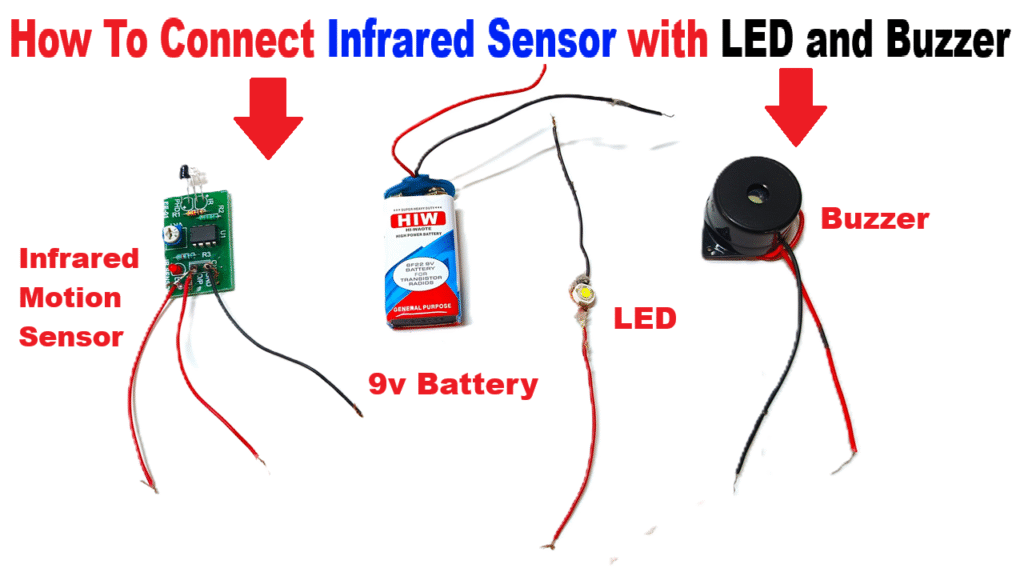
- PIR Sensor Module (Passive Infrared Motion Sensor)
- LED light (5mm or high-bright)
- Buzzer (5V–9V)
- Battery (9V)
- Connecting wires
- Switch (optional)
- Breadboard or small PCB board
- Cardboard / thermocol base for mounting
- Glue gun / tape / markers for labeling
PIR Sensor Pin Description:
A standard PIR sensor module has 3 pins:
1️⃣ VCC → +5V or +9V (Power Input)
2️⃣ OUT → Signal Output (High when motion detected)
3️⃣ GND → Ground (–)
Step-by-Step Connection Guide:
Step 1 – Prepare the Components
- Place all components (PIR sensor, LED, buzzer, battery) on your baseboard or breadboard.
- Make sure you identify the VCC, OUT, and GND pins on your PIR sensor (usually printed on the board).
Step 2 – Wiring the Power
- Connect the VCC pin of the PIR sensor to the positive terminal of the battery (9V).
- Connect the GND pin of the PIR sensor to the negative terminal of the battery.
Step 3 – Connect the Output Devices
- Connect the OUT pin of the PIR sensor to the positive leg (anode) of the LED and to the positive terminal of the buzzer.
- Connect the negative leg (cathode) of both LED and buzzer to GND (battery negative).
Tip: You can connect the LED and buzzer in parallel so both activate together.
Step 4 – Optional Switch
- Add a small on/off switch between the battery’s positive terminal and the VCC line — to turn the whole system on or off easily.
Step 5 – Test the Circuit
- Power ON the setup.
- Wait for 30–60 seconds (the PIR sensor stabilizes after powering up).
- Move your hand or walk in front of the sensor — the LED light glows and buzzer beeps when it detects motion.
- When no motion is detected, both turn OFF after a few seconds (delay time can be adjusted with the sensor’s onboard potentiometer).