In this blog post we write about making of the electricity generator working model – science project – physics project | DIY pandit #electricityproject
A DC motor can be used to create an electricity generator by connecting it to a load that converts the mechanical energy produced by the motor into electrical energy.
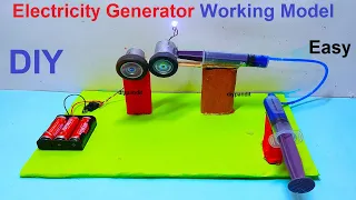
Creating a working model of a hydraulic braking system to generate electricity using syringes, a DC motor, and an LED light is an innovative way to demonstrate the principles of energy conversion and hydraulic systems. Here’s a step-by-step guide to building this model:
Materials Needed:
- Syringes (at least two)
- Tubing (to connect the syringes)
- Water
- DC motor
- LED light
- Wooden or cardboard base
- Small gears or pulleys (optional, for better mechanical advantage)
- Alligator clips (optional, for easier connections)
- Wires
- Battery pack or power source
- Tape or glue
- Scissors or craft knife
#electricitygenerator #freeenergy #freeelectricity #scienceexhibition #sciencefair #scienceproject #workingmodel #physicsworkingmodel #physics

Step by Step Video Guide on electricity generator working model – science project – physics project
- Prepare the Base:
- Cut a piece of wood or cardboard to serve as the base for your model. Make sure it’s large enough to accommodate the components and provide stability.
- Set Up the Syringes:
- Place the syringes on the base. Ensure they are securely attached and can move freely without tipping over.
- Connect the syringes with tubing to create a hydraulic system. One syringe will act as the master cylinder, and the other as the slave cylinder.
- Connect the DC Motor:
- Attach the DC motor to the base using tape or glue. Position it in a way that its shaft can be connected to the syringe or a gear/pulley mechanism.
- Connect the LED Light:
- Position the LED light on the base, preferably near the DC motor. This will represent the electrical load powered by the generator.
- Set Up the Mechanical Linkage:
- If using gears or pulleys, connect them to the syringe(s) and the DC motor shaft. This will provide mechanical advantage and increase the efficiency of the system.
- Create the Hydraulic Circuit:
- Fill one syringe with water and connect it to the other syringe using tubing. This will simulate the hydraulic fluid transferring energy from the master cylinder to the slave cylinder.
- Connect the Electrical Components:
- Connect the terminals of the DC motor to a power source, such as a battery pack, using wires. Ensure a secure connection.
- Connect one terminal of the LED light to one terminal of the DC motor. Connect the other terminal of the LED light to the power source.
- If using alligator clips, use them to make the connections between the components.
- Secure Connections and Test:
- Use tape or glue to secure the components and wires to the base. Ensure they are firmly in place to prevent movement during operation.
- Test the hydraulic braking system by pushing the plunger of the master syringe. As the hydraulic fluid transfers energy to the slave syringe, the DC motor should spin, powering the LED light.
Explanation of the Science:
- Hydraulic Braking System: When the plunger of the master syringe is pushed, it forces hydraulic fluid (water) through the tubing to the slave syringe. This movement generates mechanical energy.
- DC Motor as Generator: The spinning motion of the DC motor shaft, driven by the hydraulic system, generates electricity through electromagnetic induction when connected to a load (LED light).