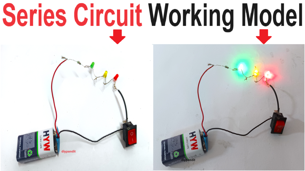
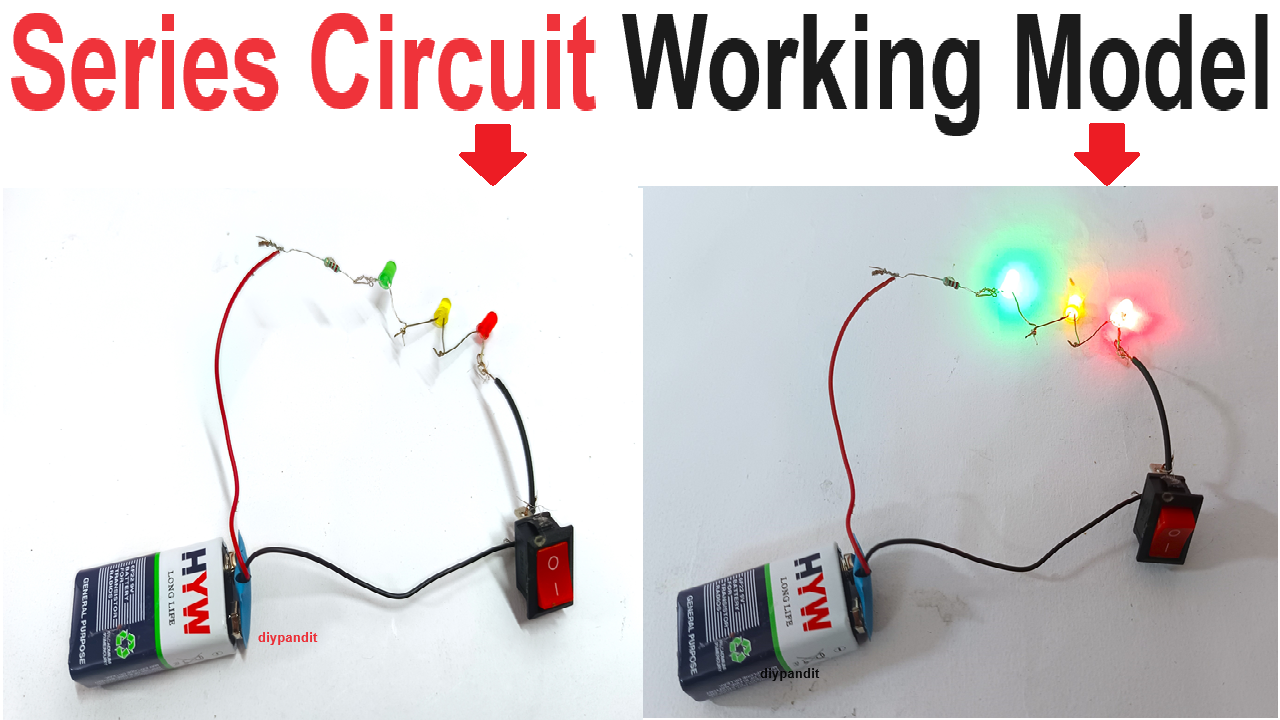
Creating a working model of a series circuit with three colored LED lights, resistors, switches, and a 9V battery can be an insightful and educational project.

Here’s a detailed step-by-step guide to help you build this model:
Materials Required:
- Three colored LED lights (red, green, blue)
- Three resistors (appropriate value for the LEDs)
- 9V battery
- 9V battery holder
- Switch (single switch or multiple switches if you want individual control for each LED)
- Wires
- Soldering iron and solder (optional)
- Alligator clips (optional)
- Glue or tape
- Scissors or a utility knife
- Markers or pens
- Wire cutters/strippers
Step by Step Video Instructions:
Step 1: Prepare the Cardboard Base
- Cut the Base: Cut a piece of cardboard to a suitable size to hold your circuit components.
- Label the Components: Mark positions for the battery, switch, resistors, and LEDs on the cardboard.
Step 2: Set Up the Components
- Battery Holder: Attach the battery holder to the cardboard at the marked position.
- Switch: Attach the switch to the cardboard at its marked position. Ensure it is easily accessible.
- LEDs: Insert the three LEDs into the cardboard at the marked positions. You can use small holes to hold them in place.
- Resistors: Attach each resistor to the cardboard near the corresponding LED positions.
Step 3: Connect the Circuit
- Connect the Battery to the Switch: Connect the positive terminal of the battery holder to one terminal of the switch using a wire.
- Connect the Switch to the Resistor: Connect the other terminal of the switch to one end of the first resistor.
- Connect Resistor to LED: Connect the other end of the first resistor to the anode (long leg) of the first LED.
- Connect LEDs in Series with Resistors: Connect the cathode (short leg) of the first LED to one end of the second resistor, and connect the other end of the second resistor to the anode of the second LED. Repeat this process for the third LED and resistor.
- Connect the Last LED to the Battery: Connect the cathode of the third LED to the negative terminal of the battery holder.
Step 4: Secure the Connections
- Check Connections: Ensure all connections are secure. You can use solder for permanent connections or alligator clips for temporary connections.
- Insulate Exposed Wires: Use electrical tape to insulate any exposed wires to prevent short circuits.
Step 5: Test the Circuit
- Insert the Battery: Place the battery in the battery holder.
- Operate the Switch: Flip the switch to turn on the circuit. All three LEDs should light up in sequence. If they do not, check the connections and ensure all components are properly connected.
Explanation
- Battery: Provides the voltage needed to power the circuit.
- Switch: Controls the flow of electricity, allowing you to turn the circuit on and off.
- Resistors: Limit the current flowing through each LED to prevent them from burning out.
- LEDs: Emit light when current flows through them. In a series circuit, the same current flows through each LED.
- Cardboard Base: Provides a stable platform to mount and organize the components.
This project effectively demonstrates how a series circuit works, with each component playing a crucial role in the functioning of the circuit.

